Harman Kardon HK730 Owners Manual - Page 4
Speakers
 |
View all Harman Kardon HK730 manuals
Add to My Manuals
Save this manual to your list of manuals |
Page 4 highlights
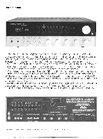
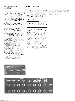
IPIIUID Aux AJx P"2°'') I O O OO -OO O O GND I MUTE AD/ ANTENNA * 0 YON -2I lAi t 'r I O 0 O 0 LEFT O O O O "MT YAM. AMPF. : 7 E Allt7i WkiN. A14, 1111--11 0-0 I- art -I FireIT • CAUTKIN - TO PREVENT ELECTRIC SHOCK. 00 NOT REMOVE MEL NO USER SERVICEABLE PARTS INSIDE. REFER SERVICING TO QUALIFIED SERVICE PEMONIEL. DO NOT REMOVE COVER OR ANY SCREWS. DESIGN CERTIFIED FOR COAPLIANCE WITH F CC RULES, PART 15. SUBPART C MEI Ale DINNEMI IT I- LIFT • • • C F LIf 8Ft:RMERS 8-26 OHMS SYSTEM C:a; I ji r- SPEAKER SYSTEM -2 --I 1 LIFT FAD .1) N1011 1 111 ' 11 10 11 NW IN MI CAUTION FOR CONTINUED PROTECTION AGAINST FIRE HAZARD, REMOVE FENNER COIN/ AND REPLACE ONLY WITH SAW TYPE IA MIN FUSE t A.CAr,u,.s.,,E, r - ,,,,A, .C..120V/60,1, liA l u:n0 ---1 0.,11TCAW 120V AC 60NE MAL 350W / Connecting Speakers to the 730: Find the Tow of four connectors on the oack panel of the 730 marked SPEAKER SYSTEM 1. Starting with either LEFT or RIGHT par of connectors, push firmly in on rne plastic head of each connector, Tevea ing an opening. Insert one bare conductor at the end of each of the lengths of wire you've prepared into each connector. Release the connector. Each conductor should be locked firmly in place in its own connector. Take the enc of this wire and connect the bare conductors to the two terminals of one of your speakers. Now (this is importan:) note :o which connector (red or black) on the 730, and to which speaker terminal. the coded side of the wire is connected. Connect the second speaker to the other two connectors under SPEAKER SYSTEM 1, ceing sure the coded side of this wire is connected to both the 730 and the speaker in the same way as the first wire. The left channel connection snould be made to the speaker placed at the left side of your listening area. The r ght channel connection should be made to the weaker placed at the right side of your listening area. Be certain [very important] all these connections are t'.ght and that all the strands of the wires are firmly seated in the connectors of the 730 and under the terminals of your speake, systems. Any loose strands of wire cou.d touch other terminals arid cause short circuits. which might cause the speaker circuit breaker to open. If you have followed these diTections, your speakers will be oroperly "phased." We will describe how to check this by ear when the other connections are completed and your system is operating. Note: Two equal lengths of w're are suggested to prevent any imbalance in the system• even if one speaker will be quite close to the 730. Later. when you put the components in your system into their final posi:;ens, you can neatly coil any excess wire and place it inconspicuously. If, now or later, you wish to connect a second pair of speakers, you can use the SPEAKER SYSTEM 2 connectors of the 730, following the procedure outlined n,eviaisty. The speakers in your system snould ALL have a rated impedance of 8 ohms or higher.* Although your 730 has been designed for use with speakers with rated impedances of 8 or 16 chms, the 730 can accommodate ONE pair of 4-ohm speakers more than adequately. You should not, however. use more than ONE pair of 4-ohm speakers. Damage to the 730 could result from such use. SPEAKERS 8-16 OHMS r - SPEAKER SYSTEM - 1-I LEFT GND GND RIGHT I I-- SPEAKER SYSTEM -2 I LEFT GND GND RIGHT I
-
 1
1 -
 2
2 -
 3
3 -
 4
4 -
 5
5 -
 6
6 -
 7
7 -
 8
8 -
 9
9 -
 10
10
 |
 |
