Harman Kardon HK730 Owners Manual - Page 5
Turntables, Antenna, Connections, Automatic, Changers
 |
View all Harman Kardon HK730 manuals
Add to My Manuals
Save this manual to your list of manuals |
Page 5 highlights
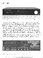
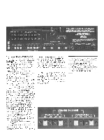
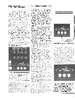
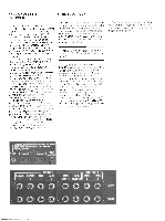
TURNTABLES OR AUTOMATIC CHANGERS The 730 has provision for connecting two record playing units. All record playing units provide two or three cables (aside from the power cord) for connection to the 730. These are the left and right channel signal cables and the ground connection. (Some turntables combine the ground connection with one of the signal cables.) The two signal cables are usually identified as "left channel" and "right channel" by a color code or tabs, or the channel identifications are molded into the insulators around the pin-type RCA connectors. Determine which of the cables is left and which right and insert them into the two corresponding receptacles on the rear panel of the 730 marked PHONO 1. Press them in as far as they will go so they are seated. snugly. If a separate ground wire is provided, connect its lug or stripped end under the knurled nut marked GND on the rear panel of the 730. The phonograph signal connections are now complete. If a second record playing unit is to be used connect it to the PHONO 2 inputs in the same manner as the first unit was connected to PHONO 1. INPUTS PHONO PHOND NJX AUX 1 2 1 2 O O O O O O O 0 ' 4111 MUTE AD.1 • • 1- 76.; ANTENNA r Fli300071 SOO Note: The 730 is designed to operate with a high quality Magnetic cartridge. If you purchased your 730 and turntable separately, be sure the turntable is equipped with a cartridge of this type. Insert the AC power cord of your turntable into the AC receptacle marked UNSWITCHED on the rear of the 730. This receptacle is "live" so long as the 730 itself is connected to a live AC outlet, regardless of whether the 730 is itself operating. Your turntable or automatic changer should be connected to this receptacle. FM ANTENNA CONNECTIONS A "T"-shaped, folded dipole antenna is provided with the 730 for FM reception. However, FM performance of the 730 will be greatly enhanced if it is connected to an outdoor antenna system. Many apartment buildings in urban areas provide a master antenna system for television reception which can often be used for FM purposes. In some suburban and rural areas, cable television systems exist that can also be used for FM reception. In fact, television antennas on private houses are often good for FM reception. Two types of wire, 300 ohm and 75 ohm, are used as lead-in for outdoor antenna systems. Either type can be connected to the 730. Find the threeconnector terminal strip on the rear panel of the 730 marked ANTENNA. If your lead-in is 300 ohm, it will be a 11/2" very flat wire with a conductor at each edge. Carefully cut about of the insulation material from the center of the 3/4" lead-in without damaging either conductor. Strip off about of insulation from each conductor and connect one of them to each of the terminals on the threeconnector ANTENNA strip under the bracket labeled 300,0,. (The term "ohm" and thasymbol "SI" have equivalent meaning.) If your lead-in is 75 ohm, you must use a matching transformer. The lead-in wire will be a single round wire with a termination consisting of a metal connector with a short length of bare, solid, copper-colored wire protruding from its center. This connector is intended to be joined to a 7552 to won matching transformer. These transformers are inexpensive and available at many television or electronic parts supply stores. Once they are joined to the lead-in they provide two 300 ohm conductors that are connected to the 730 as described above. If your 75.11 lead-in has a bare end, the appropriate connector must be attached to it so that you can use a matching transformer. Where there is only one lead-in and it must supply signal for both a television receiver and the 730, a "signal splitter" or 2-set coupler" can be used. Consult your high fidelity or television dealer for information on such devices. If no outdoor antenna is available to you, connect the lugs of the dipole antenna to the 30011 terminals. The dipole antenna will perform best if its arms are carefully extended in a straight line horizontally, and the entire antenna fixed to a wall or tacked to the back of a shelf. Dipoles are most sensitive on the axis perpendicular to the plane of the two arms so antenna position is important for optimum reception. I A ANTENNA M r Fri asoo l 900 AM ANTENNA CONNECTIONS A ferrite loopstick AM antenna is provided on the rear of the 730, which will yield good reception in many areas. It can be oriented to improve reception of distant stations. The third terminal of the ANTENNA strip is a connection for a "long wire" AM antenna. AM reception over extremely long distances can be obtained with a well-designed long wire antenna. Many high fidelity dealers, especially those who have experience with amateur and shortwave radio, can help you with a long wire AM antenna system I • ANTENNA All r For 3ooa 90 -4 WARNING: DO NOT MISTAKE THE 'TS FERRITE LOOPSTICK AM ANTENNA FOR A riANDLE. BRACKET CANNOT SUPPOR" HE WEIGHT OF THE 730. T:-E 730 SHJ._ L NEVER BE LIFTED, PULLED, OR PUSHED BY GRIPPING THE AM ANTENNA.
-
 1
1 -
 2
2 -
 3
3 -
 4
4 -
 5
5 -
 6
6 -
 7
7 -
 8
8 -
 9
9 -
 10
10
 |
 |
