Harman Kardon HK930 Owners Manual - Page 4
Installation, Procedure
 |
View all Harman Kardon HK930 manuals
Add to My Manuals
Save this manual to your list of manuals |
Page 4 highlights
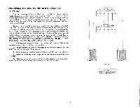
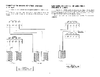
INSTALLATION PROCEDURE VENTILATION Although your new Receiver rarely develops high heat, it is still recommended that you leave the back of the cabinet open. If this is not possible, provide several large holes or slots as low down and as high up in the cabinet back as possible. As an alternative, holes may be provided in the sides, bottom or top of the cabinet. Remember that really effective ventilation requires provision for cool air to enter at the bottom and hot air to leave at the top. A minimum clearance of two (2) inches should be allowed on each side and in the rear, between the chassis and the cabinet, and three (3) inches are required above it. Isolate any accessories which might interfere with ventilation. For example, do not drape plastic or rubber covered interconnecting cable over the equipment. POWER REQUIREMENTS Connect the AC line cord to any outlet furnishing 117 volts, 50/60 cycle AC current. The voltage may vary between 105 and 125 volts. Two auxiliary AC power outlets are provided on the rear panel of your receiver, one being alive at all times and the other being live only when the power switch is ON. Any accessory equipment (tape recorder, phonograph record player, etc.) may be connected to these receptacles and if connected to the SWITCHED receptacle, this equipment will be controlled by the ON/OFF POWER switch. FUSING A fuse is a safety device used to protect the receiver against possible damage due to overload, short circuits, and excess current. This receiver employs three fuses for protection. The AC fuse, labeled 3A-3AG is used to protect the entire system. The other two speaker fuses, also 3A-3AG, are used to prevent damage to the output stage of your receiver. The output of your receiver has been designed to operate with a MAXIMUM of 3 amperes of current in each channel. Under certain conditions, it is possible to draw more than 3 amperes through the output stage which would, in turn, blow the speaker fuses. This could be caused by using multiple speaker systems where the total impedance falls below 4 ohms. Whenever you plan to operate more than two speakers simultaneously, make absolutely sure that their total load impedance WILL NOT fall below 4 ohms. In the event of fuse failure, replace ONLY with the same fuse type used. NEVER replace with a fuse of a higher rating. To do so will NOT protect your receiver and could result in severe damage to it which will not be covered under the warranty policy. SPEAKER PHASING When more than one speaker is used in a music reproducing system, the speakers must be connected in a manner which will allow them to work together. Both left and right speakers must operate in perfect unison, moving back and forth together. If the speakers are moving in opposite directions, the result will be diminished bass response and decreased realism of sound. When this occurs, the speakers are said to be out of phase. Checking for proper phase and correcting, if required, is quite simple. 1. After connecting your speakers, place the stereo receiver in the L & R or monophonic mode of operation. 2. Play a record, tape, or FM broadcast which has a single speaking or singing voice, or a solo instrument. 3. The voice or instrument should appear to be coming from an area directly between the two speakers. If the speakers are out of phase, the sound will appear to be coming from the two individual speakers. 4. If you determine that the speakers are out of phase, simply disconnect the leads from only one of the speakers and reverse them. The system will then be in phase. This completes your speaker connections. Your receiver is a solid state device which does not contain audio output transformers. It is therefore not necessary to match the impedance of your speakers to the receiver. Your unit will perform perfectly with any speaker which has an impedance of 4, 8 or 16 ohms. 3
-
 1
1 -
 2
2 -
 3
3 -
 4
4 -
 5
5 -
 6
6 -
 7
7 -
 8
8 -
 9
9 -
 10
10 -
11
-
12
-
13
 |
 |
