Harman Kardon HK930 Owners Manual - Page 8
Input, Connections
 |
View all Harman Kardon HK930 manuals
Add to My Manuals
Save this manual to your list of manuals |
Page 8 highlights
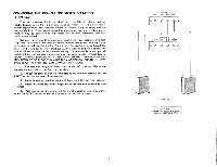
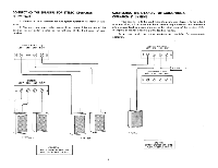
INPUT CONNECTIONS CONNECTING the FM ANTENNA The antenna input has been designed to accept either a 300 ohm balanced transmission line (300 ohm twin lead) or a 75 ohm unbalanced co-axial cable transmission line. Due to the exceptionally high sensitivity of your receiver, a 48" wire is sufficient for all but the most difficult locations. When using the 48" antenna, connect one end of the 48" wire to either FM antenna terminal. Horizontal placement of the antenna will yield optimum reception. The antenna may be tacked to the back of the molding behind the equipment or to the shelf you use. As FM signals are in the same broadcast frequency range as TV signals, they arc affected by the same external conditions. Just as TV reception is improved, you can improve your FM reception with on external antenna. When using an external antenna, connect both leads of the antenna wire to the two 300 ohm FM antenna terminal posts on the rear of your receiver. When using a 75 ohm Coaxial Cable connect between the 75 ohm and GND terminal, with the outer conductor or shield of the cable connected to the GND terminal. CONNECTING THE AM ANTENNA The AM loopstick fastened to the rear of your receiver comprises all the antenna usually required for normal signal areas. In more remote locations an additional outdoor antenna may be required. This should consist of a single wire, as long as is reasonably practical. It must be kept away from large metal objects, power lines or electrical machinery to insure reception without extraneous noise. Attach this length of wire to the AM terminal of the ANTENNA terminal strip. PREAMP OUT AND AMP IN RECEPTACLES These receptacles are intended for use with any necessary equipment designed to be installed between a preamplifier and power amplifier. This includes such equipment as electronic audio equalizers, reverberation units, and a new quadraphonic processor offered by Harman-Kardon. In order to make use of this -facility, simply disconnect the two patch cords connected to these receptacles and follow the instructions supplied with the accessory equipment. NOTE: When no accessory equipment is being used, the two patch cords MUST he installed in order to use your receiver. PHONO 1 and PHONO 2 There are two sets of low level phono receptacles on the rear panel of your receiver. They are designed for use with any magnetic pickup with a nominal impedance of 42,000 to 52,000 ohms. This special convenience permits you to connect a record changer and a manual turntable simultaneously, and to switch between them with the function selector located on the front panel. Since both low level inputs are identical and each has been compensated for the RJAA recording curve of today's modern recordings, either or both may be used. When connecting a stereo record player (magnetic pickup) connect both leads to either the Phono 1 or Phono 2 LEFT and RIGHT input receptacles on the rear of the receiver chassis. When connecting a monophonic record player (magnetic pickup) connect the single lead to either the Phono 1 or Phono 2 LEFT or RIGHT input receptacle. GROUND CONNECTION Under certain conditions it may be necessary to provide a common "ground" between your receiver and your other associated equipment. This may be accomplished by using the GND terminal located on the rear panel of your receiver. AUX INPUTS Your receiver has two pair of AUX INPUT receptacles for use with high level program sources; ceramic or crystal pickup, reel-to-reel tape recorder, cassette tape recorder, TV or a second stereo tuner. When connecting a stereo record player (ceramic pickup) connect both leads to either the AUX 1 or AUX 2 LEFT and RIGHT input receptacles on the rear of the receiver chassis, When connecting a monophonic record player (ceramic pickup) connect the single lead to either the AUX 1 or AUX 2 LEFT or RIGHT input receptacle. When connecting a stereo tape recorder connect both output cables to either the AUX 1 or AUX 2 LEFT and RIGHT input receptacles on the rear of the receiver chassis. When connecting a monophonic tape recorder connect the single output lead to either the AUX 1 or AUX 2 LEFT or RIGHT input receptacle. In order to make a recording connect the input cable (if monophonic) or cables (if stereophonic) to either the TAPE OUT 1 or TAPE OUT 2 receptacles on the rear of the receiver chassis. TAPE MONITOR 1 and TAPE MONITOR 2 There are two pair of tape monitor receptacles on the rear of your receiver. Either one or both pair of receptacles may be used to monitor your tapes as you make a recording, provided your tape recorder or recorders have separate record and playback heads. Connect the LEFT and RIGHT output cables of your tape recorder to the TAPE MONITOR 1 or 2 input receptacles. Complete operation is explained in detail in the paragraph TAPE MONITOR SWITCH. 7
-
 1
1 -
2
-
 3
3 -
 4
4 -
 5
5 -
 6
6 -
 7
7 -
 8
8 -
 9
9 -
 10
10 -
 11
11 -
 12
12 -
 13
13
 |
 |
