Harman Kardon ST360A Owners Manual - Page 5
adjustable
 |
View all Harman Kardon ST360A manuals
Add to My Manuals
Save this manual to your list of manuals |
Page 5 highlights
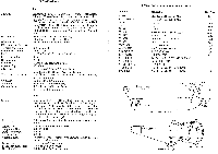
Circuits: Sensitivity: Selectivity: Discriminator Peak to Peak Separation: Frequency Range: Drift: Image Rejection: IF Rejection: Limiter: Antenna Input: Distortion: Frequency Response: Hum Level: Radiation: Output Level: Circuits: Sensitivity: Selectivity: Frequency Range: Image Rejection: IF Rejection: Antenna Input: Distortion: Frequency Response: Hum Level: SPECIFICATIONS FM Armstrong circuit with zero time constant Gated Beam Limiter, Foster-Seeley Discriminator, Automatic Frequency Control and Bar Type Tuning indicator. The RF section consists of a Shaded Grid Low Noise, High Gain VHF Tetrode, High Gain Pentode Mixer followed by three Wide Band IF stages, Limiter, Wide Band (0.6 MC) Discriminator and Anode Follower Output. put. 0.95 microvolts, ( 20 db quieting ). 1.9 microvolts. ( 30 db quieting ). 240 KC Bandwidth: 6 db down. 0.6 megacycles. 88-108 M.C. -± 20 KC AFC off; ± KC AFC on. 40 db 70 db Gated beam, constant output. 300 ohms Less than 0,1% IM at 30% modulation. Less than 0.25% IM at 100% modulation. db 20-20,000 c.p.s. including standard 75 microsecond de-emphasis. 60 db below 100% modulation. Within FCC requirements. 1.5 volts for 100% modulation. 5 volts for 30% modulation, AM Low noise, high gain RF pentode followed by a pentagrid converter, two broad band IF transformers, separate tuned AVC amplifier, infinite impedance detector and adjustable 10 KC whistle filter. The separate AVC amplifier circuit avoids overloading of the detector improving linearity. Exclusive noise filter for noisefree long distance reception. 20 microvolts per meter. Terminal sensitivity 4 microvolts. 16 KC Bandwidth: 6 db down. 530-1640 KC 55 db 55 db Built in Ferrite Loopstick with low impedance Terminal for external antenna. Less than 0.8% harmonic. ± 3 db 20-8,000 cycles. 55db below 80% modulation. Part No. 1362133 STCOM3270 2923271 2923272 2923273 3223626 2923275 3223629 3223624 HC33901 ZCOM3291 STCOM3279 GT2493012 GT2503045 GT2503052 GTCOM3346 JV2923213 JV2923214 REPLACEMENT PARTS FOR MODEL ST35O Description SEL RECTIFIER 65 MA SEL RECTIFIER 75 MA LYTIC LYTIC LYTIC POWER TRANSFORMER FUNCTION SWITCH LOOPSTICK ANTENNA DIAL GLASS FUSE HOLDER 3 AG 3 AMP FUSE AM OSC COIL RF TRANSF. 1st, 2nd, 3rd, 4th FM IF TRANSF. DISC TRANSF. IF TRANSF. FM TUNING CAPACITOR AM TUNING CAPACITOR List Price 1.65 1.75 3.00 2.60 2.50 12.00 7.50 2.25 1.00 .75 .10 .75 1.50 1.50 2.00 1.50 5.35 5.85 TUNING CAPACITOR CLOSED O TUNING SHAFT AM TUNING DRUM AM STRINGING DIAGRAM FM TUNING DRUM A TUNING CAPACITOR CLOSED AM TUNING • ti DRUM TUNING SHAFT b • F M STRINGING DIAGRAM FM TUNING DRUM
-
 1
1 -
 2
2 -
 3
3 -
 4
4 -
 5
5 -
 6
6
 |
 |
