Harman Kardon ST5 Owners Manual - Page 4
the signal
 |
View all Harman Kardon ST5 manuals
Add to My Manuals
Save this manual to your list of manuals |
Page 4 highlights
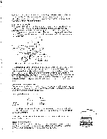
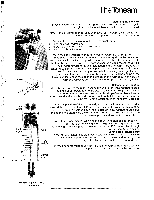
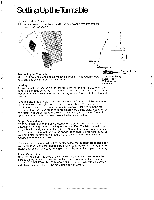
Additional tonearms complete with mounting hardware, Harman Kardon model number CH-5W, are available through your Harman Kardon dealer. With additional tonearms, you can use more than one cartridge without having to remount for each change. Adjusting Arm Length The stylus will track in perfect tangency to the record groove when the arm length is properly adjusted. Loosen the mounting plate screw on the underside of the tonearm. Dress the signal wires forward and place the cartridge gauge on the arm as shown. The notch of the gauge fits over the black "T" bar, while the locating pin of the gauge fits in the corresponding hole in the arm. Crosshair Marking Adjustment P n Notch Locating Hole Mounting Plate Screw "T" Bar Metal Hum Shield Note: Gauge fits "inside" walls of hum shield. The cartridge assembly and mounting plate can be moved back and forth if the mounting plate screws and hex nuts are loose enough. Move the assembly so that the stylus lines up with the crosshair marking on the top of the cartridge gauge. Then tighten the mounting plate screw (access is provided through the large hole in the cartridge gauge) and the two cartridge mounting screws to lock your adjustment. Check that the cartridge has not twisted and that the stylus is visually in line with the center of the tonearm tube. Connecting the Signal Wires Connect the signal wires of the tonearm to the appropriate terminals on your cartridge. Use extreme care as the wires are delicate. Using tweezers or long- nose pliers will make connection easier. The signal wires are color coded: Signal Ground Left Channel WHITE BLACK Right Channel RED GREEN The cartridge may have a different color code or other marking system to identify its terminals. Consult the instructions supplied with your cartridge for this information. When you have connected the signal wires, the tonearm will be ready to mount in the carriage. Installing Leveling Feet Remove the four (knurled) leveling feet from the upper foam packing and install on the male threaded adapters attached to the isolators. Leveling instructions are discussed in the following paragraphs.
-
 1
1 -
 2
2 -
 3
3 -
 4
4 -
 5
5 -
 6
6 -
 7
7 -
 8
8
 |
 |
