Harman Kardon TA10 Owners Manual - Page 2
Phonograph, Connections
 |
View all Harman Kardon TA10 manuals
Add to My Manuals
Save this manual to your list of manuals |
Page 2 highlights
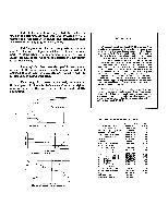
FM ANTENNA A short length of ordinary wire, connected to the terminal marked FM will prove adequate in most installations. A loop of wire, approximately 36 inches long, connected between "FM" and "G" and hung inside the cabinet will prove useful in increasing the rejection of spurious signals. In those situations requiring an external FM antenna, connections should be made between "G" and "FM." A single dipole will be useful when stations to be received are located in opposite directions from each other. A non-directional dipole should be used if the stations are located in dispersed directions. A folded dipole antenna with reflector will provide maximum efficiency and may increase the number of distant FM stations your TA-10 can receive. POWER Plug the power cord into any outlet furnishing 117 volts, 60 cycles house current. The exact voltage is relatively unimportant, and may vary between 105 and 125. Be sure, however, that you have 60 cycle AC power. A convenience outlet at the rear of the Solo may be used for your record player which will then be turned on or off by the Solo power switch. PHONOGRAPH CONNECTIONS Any type of record player will operate with the Solo. To derive maximum enjoyment it is suggested that a high quality pickup cartridge and a rumble -free turntable be used. Two classes of pickup cartridges are in general use: Magnetic (GE, Pickering, Fairchild, and Audak) and Crystal (including the newly developed ceramics). While any type of cartridge may be used with the Solo, it is strongly urged that the magnetic type be selected. It should be plugged into the receptacle marked "PHONO." Connect crystal or ceramic cartridges to the receptacle marked "AUX. " A word of advice: The useful life of a phonograph needle is quite short, ranging from 15 minutes to several hours. In addition to degradation of tone quality as the needle wears, the strong possibility exists that valuable records will be damaged if worn needles are not promptly replaced. The purchase of a diamond, which has extremely long life, is therefore a worthwhile investment. The power cord of the turntable may be plugged into the auxiliary AC power outlet on the rear of the Solo. It is sometimes advisable to ground the phonograph chassis to the receiver, to reduce hum or other unwanted noises. This may be accomplished by the use of any type of wire, one end connected to the "G" terminal of the "ANTENNA" or "SPEAKER" terminal strips, the other end connected to the metal framework of the phonograph. AUXILIARY INPUT An extra input is provided for auxiliary high level equipment such as a tape recorder or television tuner. This input is located on the rear of the Solo chassis. If 2 you are using a ceramic or crystal cartridge make certain to connect your phonograph output to this input. TAPE OUTPUT A receptacle marked "Tape Out" is located on the rear of the chassis. This is used to provide output to a tape recorder or other auxiliary equipment. Any program material appearing at the speaker terminals also appears at the "Tape Out" receptacle, but unmodified by the volume or tone controls. This makes it possible to record programs with the proper recording equalization (as determined by your tape recorder) while simultaneously listening to the program with the proper tone control, contour and loudness settings. SPEAKER CONNECTIONS A unique method of connecting one or two loudspeakers is incorporated in the Solo in order that you derive maximum enjoyment from this superlative instrument with any of today's fine speaker systems. For those using one speaker connect the speaker leads to terminals "G" and "A" on the three screw terminal strip at the rear of the chassis marked "SPEAKER. " For speakers with an impedance of 12 to 24 ohms place the Impedance Selector Switch located at the rear of the chassis in position 1. For speakers with an impedance of from 4 to 12 ohms place the Impedance Selector Switch in position 2. The front panel Speaker Selector Switch should then be placed in position "A." If you wish to feed two speakers with the Solo and use either one or both together connect the second speaker to terminals "G" and "B" on the speaker terminal strip. For best operation both speakers should have the same impedance, although a slight mismatch will not affect the overall response. To select speaker A slide the front panel Speaker Selector Switch to position "A." To select speaker B slide the switch to position "B." To feed both speakers at the same time slide the switch to the position marked "AB." Due to the fact that the Speaker Selector Switch changes the transformer connections as well as the speaker connections in any position either or both speakers will be fed at the correct matching impedance and optimum results will be obtained. AUTOMATIC FREQUENCY CONTROL (AFC) FM Broadcasting, by its very nature, eliminates almost all natural and man-made static. However, the characteristics of FM which make this possible also make for problems in tuning. The HARMAN-KARDON Solo incorporates an effective Automatic Frequency Control (AFC) circuit that overcomes these problems and insures proper tuning even if the manual tuning is not accurately done. The following experiment will lead to an understanding of AFC, and the fuller enjoyment of the Solo. Tune across the FM scale with the function switch into the FM-AFC position. Note how the stations "pop"
-
 1
1 -
 2
2 -
 3
3 -
 4
4 -
 5
5 -
 6
6 -
 7
7 -
 8
8
 |
 |
