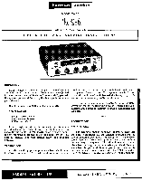
Harman Kardon TA10 Owners Manual - Page 5
Warranty, Replaceable, Parts
 |
View all Harman Kardon TA10 manuals
Add to My Manuals
Save this manual to your list of manuals |
Page 5 highlights
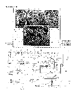
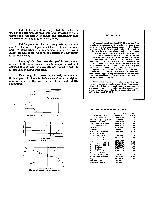
This photograph shows the printed circuit boards used in the Harman-Kardon Solo and indicates to some degree the complexity of design and painstaking care required in the planning of such a unit. FM frequencies, by their very nature, require careful placement of parts and leads. In conventional point to point wiring, misplacement of a wire, even a slight amount from its correct position will adversely affect operation. The amplifier has been designed to use printed circuits in those areas where' each component and each connecting lead must be carefully positioned in order to afford best possible operation. This design form results, we feel, in providing the best possible characteristics and reflects the highest state of the art in the construction of fine high fidelity equipment. WARRANTY We warrant each Solo, Model TA-10 to be free from defects in material and workmanship under normal use and service, and in accordance with the conditions herein below set forth, for a period of 90 days from date of delivery to the original purchaser, and agree to replace or repair any part or parts returned to us within said 90 days, with transportation prepaid, and which our examination shall disclose to our satisfaction to have been thus defective. This warranty does not include free labor, nor is it applicable to any instrument which shall have been repaired or altered in any way so as in our judgment to affect its stability or reliability nor which has been subject to neglect, misuse, abuse, negligence or accident nor which has had the serial number altered, effaced, or removed. Neither shall this warranty apply to any instrument which has been connected otherwise than in accordance with the instructions furnished by us. This warranty is expressly in lieu of all other warranties, express or implied, and of all other obligations or liabilities on our part, and we neither assume nor authorize any representative or other person to as- • sume for us any other liability, in connection with the sale of the Model TA-10 Solo. vOLT 0 CO 2 0 5. I 2K FM detector output voltage characteristics INTERMODULATON DISTORTION (MEASURED AT 60,000 CYCLES, AT • TOO 12 EPRED OUT UT IN WATTS intermodulation distortion characteristics 20 -1.44-1- Dab .10 10 N 1114NOvEN 50 00 200 500 EX 2 5 KM 20M filE011,N, IN ',Yr CS DER SE Olin 5 Phonograph equalization characteristics. LIST OF REPLACEABLE PARTS HARMAN-KARDON DESCRIPTION PART NO. Antenna Loopstick GL781479A Tuning Ring, Loopstick P481329A Switch, Function ER901598A Transformer, Power FT901572A Transformer, Output FT 901645A Dial Glass P901575A Pointer Z24773 Condenser, Variable JV781468D Capacitor, Elect. 40-60-60/150 V. JE781436C Transformer, FM, IF GT781491A Transformer, FM, Disc. GT781492A Transformer, AM, IF GT781493A Transformer, FM, IF GT781570A Tone Control RV901581A Tone Control RV901582A Volume Control RV901583A Capacitor, Elect. 40-20-10/350, 100/150 JE621281D Front Panel Assembly C901629A Cage P901591A Instruction Sheet L901593 Mounting Template L901594 LIST PRICE 2.30 .15 1.30 11.45 5.40 .60 .20 6.30 2.50 1.60 2. 00 1.50 1.45 .60 .60 .90 2.40 6.80 11.00 .75 .15
-
 1
1 -
 2
2 -
 3
3 -
 4
4 -
 5
5 -
 6
6 -
 7
7 -
 8
8
 |
 |
