Harman Kardon TA260 Owners Manual - Page 4
Channel, Output, Stereo, Headphone, Output, Connecting, Antenna
 |
View all Harman Kardon TA260 manuals
Add to My Manuals
Save this manual to your list of manuals |
Page 4 highlights
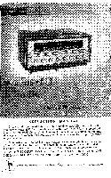
terminals are terminated into speakers or into a speaker and resistive load. For example, if you have only one speaker, attach it to the Left Speaker Output connections and connect a 4, 8 or 16 ohm 25 watt wirewound resistor to the Right Speaker Output connections. This will assure proper loading of the output stage and will prevent damage to the output tubes. A more satisfactory solution would be to connect an additional speaker for monophonic listening instead of the or 16 ohm resistor. 3rd Channel Output: One of the features of the TA260 is a third channel output jack. This output can be used for a remote basic amplifier-speaker system in addition to a regular stereo system, or as a center channel output for a basic amplifier-speaker system along with your regular stereo installation. In the latter arrangement, it serves to eliminate especially troublesome hole-in-the-middle problems due to acoustic difficulties. The third channel output is one volt. The jack is located just above the rear panel on the top of the chassis. Use up to 25 feet of shielded lead equipped with standard phono plugs to connect the jack to the third channel amplifier input. All of the front-panel controls on the TA-260 also control the third channel output, with the exception of the Mode-Blend Control and the Stereo NormalReverse Switch. Stereo Headphone Output Jack: Another feature of the TA260 is a special jack on the rear panel for plugging ;n a set of stereo headphones. When the headphones are plugged in, the speakers are automatically disconnected. The jack can accept headphones with the same impedances as are available for speakers. Simply connect the speaker impedance selector leads to the 4, 8, or 16 ohm terminals on the rear panel in accordance with the impedance rating of your headphones. The headphone plug required for this jack is the Switchcraft Type 230F, or equivalent. It is important to use the right plug for this purpose for proper operation. Connecting The FM Antenna: Due to the exceptionally high FM sensitivity of the TA260, the 48" piece of wire supplied with the unit will be sufficient antenna for all but the most difficult locations. One end of this wire should be stripped of insulation and attached to the rear screw terminal marked FM on the Antenna Terminal strip located on the rear of the chassis. The other end of this wire should be extended horizontally along the cabinet or table. Horizontal placement of the antenna wire provides proper polarization for optimum reception. If an outdoor antenna is required to "reach" for distant stations, use a folded dipole or Yagi specifically cut for the FM band. A homemade 300 ohm "T" type antenna is not satisfactory and should not be used as a substitute for the 48" piece of wire supplied with the set. The "1" type antenna has a tendency to pick up extraneous noise. TV antennas are rarely satisfactory as they are not cut for the FM band and have a tendency to introduce ignition noise and other interference into the tuner circuit. They are not recommended except under unavoidable circumstances. Usually better results can be obtained with the 48" piece of wire. When using an outdoor antenna, attach the 300 ohm lead-in wire (twisting it 4-5 times for each running foot) to the antenna terminals on the rear of the TA260 marked FM and G. Connecting The AM Antenna: The AM swivel loopstick antenna on the rear of the TA260 chassis comprise', all the antenna required for normal signal areas. In more remote locations an
-
 1
1 -
 2
2 -
 3
3 -
 4
4 -
 5
5 -
 6
6 -
 7
7 -
 8
8 -
 9
9 -
 10
10 -
11
-
12
-
13
-
14
-
15
 |
 |
