Harman Kardon TX20 Owners Manual - Page 3
receptacle
 |
View all Harman Kardon TX20 manuals
Add to My Manuals
Save this manual to your list of manuals |
Page 3 highlights
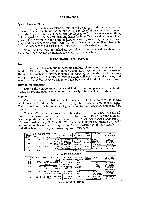
Power Requirements: Plug the AC cord into any outlet furnishing 117 volts 50 or 60 cycle AC current. The voltage may vary between 105 and 125 volts. REAR PANEL CONNECTIONS OO O AM G FM AUDIO OUTPUT • • II7 VAG 3/4 A-3AG FUSE INSIDE 60'1, 30W FM MULTIPLEX Audio Output: REAR PANEL MODEL TX20 Two AUDIO OUTPUT receptacles are located on the rear of the chassis. They are used to connect the tuner to the amplifier for normal monaural operation. These two receptacles are electrically connected in parallel. One AUDIO OUTPUT receptacle may connect to the tuner input on your amplifier, and the other may connect directly to your tape recorder. Connecting for AM-FM Monaural Operation: Connect a shielded cable between one of the AUDIO OUTPUT jacks and the tuner or Aux input jack on your amplifier. The length of this cable may be up to 30 feet. Connecting for FM Multiplex Operation: In those localities where FM Multiplex broadcasting is available, attach your multiplex adapter to the jack on the rear of the TX20 tuner marked FM MULTIPLEX. The outputs of your multiplex adapter are then connected to the left and right channel tuner inputs on your stereophonic amplifier. This is only one method of FM multiplexing. It is suggested you follow the instructions supplied with your multiplex adapter for proper hookup of your adapter. Connecting the FM Antenna: Due to the extremely high FM sensitivity of the Model TX20, the 48" piece of wire furnished with the set will be sufficient antenna for all but the most difficult locations. One end of this wire should be fastened to the "FM" terminal of the Antenna Terminal Strip, the other end left free and extended as may be convenient. It may be tacked or stapled to the rear of the bookcase or equipment cabinet if necessary. If, for some reason, it is necessary to utilize a different FM antenna, we have listed for your convenience the following suggestions: 1. Special outdoor FM antennas may be used. These come in various types. For extremely difficult locations an in-line Yagi cut for the FM band or equivalent may be necessary. For reception of FM stations scattered in many directions, the non-directional antenna may be used. This nondirectional type is known as a double dipole and consists of two folded dipoles placed at right angles to each other. 2. Your present TV antenna may be used to obtain a maximum FM signal. A special antenna coupler or knife switch should be used when joining the FM line to the television antenna. Attach one lead of the 300 ohm lead-in wire to the "FM" terminal and the other lead to the "G" terminal.
-
 1
1 -
 2
2 -
 3
3 -
 4
4 -
 5
5 -
 6
6 -
 7
7 -
 8
8
 |
 |
