Harman Kardon TX20 Owners Manual - Page 5
ADJUSTMENTS, System, Noise, MAINTENANCE, REPAIRS, Routine, Maintenance, Repair
 |
View all Harman Kardon TX20 manuals
Add to My Manuals
Save this manual to your list of manuals |
Page 5 highlights
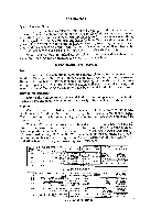
ADJUSTMENTS System Hum or Noise: In any high fidelity installation, hum may be caused by the interconnection of a record changer, tuner and amplifier, as a result of the cables and different grounds. A good way to eliminate this problem is to first disconnect everything but the speakers from the amplifier, and listen for hum. Try reversing the amplifier power plug. Now plug in the tuner. If hum appears, try reversing the tuner power plug, and try connecting a wire from the tuner chassis to the amplifier chassis. In this way, connect the record player, tape deck and other devices in turn. Note that hum may be picked up by defective interconnecting cables, and by interconnecting cables running too close to power cables. MAINTENANCE AND REPAIRS Fuse: In the event of a potentially damaging failure of tubes or components, the Model TX20 is protected by a ,X1 ampere, type 3AG fuse, located on the rear of the unit. If this fuse is blown, it should be replaced only with one of the same rating. Replacing with a fuse of higher rating will not protect the tuner, and may result in severe damage, which will not be covered by the factory warranty. Routine Maintenance: Due to the conservative design and high quality components of the Model TX20, no routine maintenance other than yearly tube checking is advised. Repair: Only the most qualified service technician should be employed, as special equipment and training is required to properly service a high fidelity tuner. This manual contains information of great value to the repairman, and should be kept available. Factory Warranty Stations are maintained in most major cities. For the address of the nearest one, or for any other information relating to your HarmanKardon products, write to the attention of the Customer Service Department, Harman-Kardon, Inc., 520 Main St., Westbury, N. Y. Be sure to include the model and serial number of the set in question. A short description of your complete installation is often of help in answering your questions. FUNCTION SIGNAL GENERATOR SIGNAL SWITCH INPUT SETTING FREQ. MOD. POINT AM 455 KC 30% AM AM RF GANG AM 1500 KC 30, AM AM ANT. TERM. AM 600 KC 30% AM AM ANT. TERM. AM 1500 KC OUTPUT CONNECT DIAL ADJUST INDICATOR INDICATOR SETTING TO: AC-VTVM TUNER 1600 KC 2 AM IF OR SCOPE OUTPUT TRANS. AC-VTVM TUNER 1500 KC OSC & ANT OR SCOPE OUTPUT .TRIMMERS AC-VTVM TUNER 600 KC OSC COIL OR SCOPE OUTPUT & LOOPSTICK REPEAT STEP 2 OUTPUT INDICATION MAXIMUM OUTPUT MAXIMUM OUTPUT MAXIMUM OUTPUT AM ALIGNMENT PROCEDURE I FUNCTION SIGNAL GENERATOR SIGNAL OUTPUT CONNECT DIAL ADJUST OUTPUT SWITCH INPUT INDICATOR INDICATOR SETTING INDICATION SETTING FREQ. MOD. POINT TO: FM 10.7 MC 300KC FM FM MIXER AC-VTVM TEST 3 FM IF MAX GAIN & 60 CPS GANG OR SCOPE POINT TRANS. SYMMETRY FM 10.7 MC 300KC FM FM MIXER AC-VTVM TUNER DISCR. S PATTERN 60 CPS GANG OR SCOPE OUTPUT TRANS. OF MAX GAIN & SYMM. FM 106 MC 300KC FM FM ANT. AC-VTVM TEST 106 MC 106 MC OSC MAXIMUM 60 CPS TERMINAL OR SCOPE POINT RF, MIXER OUTPUT TRIMMERS FM 90 MC 300KC FM FM ANT. AC-VTVM TEST 90 MC OSC, RF, MAXIMUM 60 CPS TERMINAL OR SCOPE POINT MIXER COILS OUTPUT FM ALIGNMENT PROCEDURE
-
 1
1 -
 2
2 -
 3
3 -
 4
4 -
 5
5 -
 6
6 -
 7
7 -
 8
8
 |
 |
