Hayward Aqua Plus® Model: PL-PLUS-16V Installation - Page 21
Pro Logic Output, VSP Address - aqua plus 105
 |
View all Hayward Aqua Plus® manuals
Add to My Manuals
Save this manual to your list of manuals |
Page 21 highlights
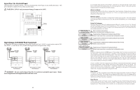
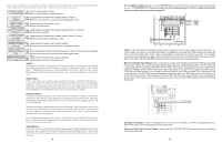
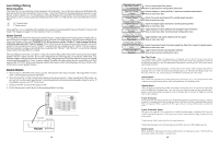
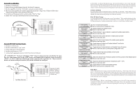
Pool/Spa Config. + to view/change Push to access Pool/Spa options Move to previous/next configuration menu Pool/Spa Setup Pool and Spa-Std Rotates between Pool and Spa-Std (default), Pool and Spa-Dual, Pool Only, and Spa Only options Move to next menu item if "Pool and Spa-Dual" is selected Heaters Toggle between Htr1=Spa, Htr2=Pool (default) and Shared Heaters Htr1=Spa,Htr2=Pool Move to next menu item if "Pool and Spa-Std" is selected Spa - CountDn Adjust time setting (Manual On/Off, 0:05, 0:10, 0:15..., (default is 4:00)) 00:30 Move to next menu item if "Pool and Spa-Std or Dual" is selected Spa Spillover Toggle between Enabled and Disabled (default) Spa Spillover Enabled Move to next menu item or previous/next configuration menu if "Pool and Spa-Std or Dual" is selected and if "Spa Spillover" is enabled Filter Operation Toggle between Pool Only (default) and Spa Spillover options Spa Spillover Move to previous/next configuration menu if "Pool Only" or "Spa Only" is selected V1=Aux1, V2=Aux2 Toggle between Enabled and Disabled (default) Disabled Move to previous/next configuration menu if "Pool and Spa-Std" is selected Filter Off Valve Toggle between Enabled (default) and Disabled Change: Enabled Move to previous/next configuration menu Pool/Spa Setup If "Pool Only" or "Spa Only" are selected, then the pool/spa valves are not needed and pushing the POOL/SPA button on the display/keypad will have no effect. If "Pool and Spa-Std" is selected, then the pool/spa suction and return valve actuators should be connected to the Pro Logic. Pressing the POOL/SPA button on the display/keypad will allow the homeowner to alternate between pool and spa operation. If "Pool and Spa-Dual" is selected, then only the Pool/Spa return valve actuator should be connected to the Pro Logic. Heaters This menu will only appear if Pool/Spa setup is set to "Pool and Spa-Dual". This allows the heater(s) to either be shared between the pool and spa ("Shared" selected) or for Heater1 to be dedicated to the spa and Heater2 to be dedicated to the pool ("Htr1=Spa, Htr2=Pool" selected). Spa CountDn This menu will appear only if Pool/Spa Setup is set to "Pool and Spa-Std". This setting is the time, after you manually switch the Pool/Spa valves to "Spa Only", until the Pro Logic automatically returns the valves to their previous positions. It is programmed in increments of 5 minutes, from "Manual On/Off" (0 minutes) to "21:00" (21 hours). The filter is forced on during this time period. Spa Spillover When spa spillover is "Enabled" and "Pool and Spa-Std", the homeowner will be able to rotate through "Pool Only" (both suction and return valves switched to pool), "Spa Only" (both suction and return valves switched to spa) and "Spillover" (suction valve switched to pool and return valve switched to spa) by successive presses of the "Pool/Spa" button. For "Pool and Spa-Dual", only "Pool Only" and "Spillover" are available. Filter Operation If "Spa Spillover" is selected, the Pro Logic will automatically switch the pool/spa suction and return valves to "spillover" at the start of the programmed pool filtering time period or when the superchlorinate function is turned on. The valves will remain in this position for the remainder of the superchlorinate period. This option is usually preferable because both the pool and spa water will be filtered and sanitized. 25 STA-RITE Heater 1. Turn power off to heater. 2. Remove upper jacket and open the control box. 3. Remove the jumper for the "fireman's switch. 4. Wire to the Aqua Plus 16v using wire rated for 105°C minimum. Fireman's Switch Operating 'Control Terminal Board STA-RITE Hayward Variable Speed Pump (VSP) Wiring and Address Setting Refer to your TriStar or EcoStar manual(s) for proper low voltage communication wiring between the Pro Logic and the Hayward Variable Speed Pump. A pump address must be configured for each VSP used in the system. This address is entered into the VSP's configuration menu. Refer to the table below to determine which address to use for your specific pump and Pro Logic. Select the proper address based on which output will be used and the model VSP you are configuring. Pro Logic Output This is the output used to control the VSP. Note that the VSP should be wired to this output's corresponding relay. VSP Address This is the name that should be selected under "Set COMM bus address" (EcoStar) or "*H.Comm ADDR." (TriStar) within the VSP's Configuration Menu. FILTER - all Pro Logic models "001" - Tristar "Pool Filter" - EcoStar AUX1 - all Pro Logic models Dual Equipment Spa Filter - all models "002" - Tristar "Aux1 / Spa Filter" - EcoStar LIGHTS - all Pro Logic models "Lights Button" - EcoStar only AUX2 - all Pro Logic models AUX3-AUX6 - PS8 & PS16 models AUX7-AUX14 - PS16 models Aux2-Aux14 - EcoStar only (use same as Pro Logic Output) 18
-
 1
1 -
2
-
3
-
4
-
5
-
6
-
7
-
8
-
9
-
10
-
11
-
12
-
13
-
14
-
15
-
 16
16 -
 17
17 -
 18
18 -
 19
19 -
 20
20 -
 21
21 -
 22
22 -
 23
23 -
 24
24
 |
 |
