Hayward Aqua Solar GL-235 Model: GL-235 - Page 3
Troubleshooting - solar controller
 |
View all Hayward Aqua Solar GL-235 manuals
Add to My Manuals
Save this manual to your list of manuals |
Page 3 highlights
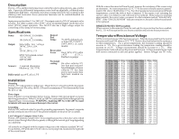
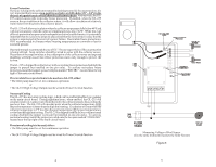
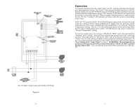
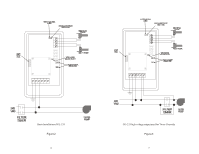
Troubleshooting No Power Indicator • Check main power circuit breakers. • Check fuse Fuse Replacement The GL-235 is protected by a fuse located on the left side of the main circuit board. Replace the fuse with a 2A, type ATO-2 fuse, readily available in most automotive or electronics stores. If "Heating" is always on Disable recirculate freeze protection if enabled. Check that the switch is in the "AUTO" position. Next verify that the control circuitry is operating properly by disconnecting the solar sensor from the terminal block. The "Heating" LED should go off and the "CHECK SENSOR" LED should begin to blink. If "Heating" remains on, there is an internal circuit failure and the GL-235 will have to be returned for repair. If "Heating" never comes on Verify that the switch is in the "AUTO" position, the desired pool temperature dial is set higher (hotter) that the actual pool temperature, and the solar sensor is warmer than the pool water. Also check that the switch on the valve actuator is NOT in the "OFF" position. Disconnect the pool sensor from the terminal block and verify that the "CHECK SENSOR" LED turns on. If the "CHECK SENSOR" LED does not turn on, there is an internal failure and the GL-235 will have to be returned for repair. Reconnect the pool sensor and verify that the "Check Sensor" LED turns off. Next, disconnect the "solar" sensor from the terminal block and verify that the "CHECK SENSOR" LED begins to blink. If the "CHECK SENSOR" LED does not begin to blink, there is an internal failure and the GL-235 will have to be returned for repair. "CHECK SENSOR" indicator on If the "CHECK SENSOR indicator is on and NOT blinking, there may be a possible open circuit or short circuit with the pool sensor. Using a voltmeter, measure the DC voltage across the terminals of the pool sensor as indicated in figure 5. If the voltage is close to zero volts, the sensor has a short to ground. Remove the sensor from the terminal block and measure the voltage across the pool terminals again. If the voltage is still close to zero volts, there is an internal short and the unit must be returned for repair. If the voltage is close to five volts, the pool sensor itself may be at fault. With the sensor disconnected from the unit, measure the resistance of the sensor using an ohmmeter. At room temperature (25ºC/77ºF) the sensor should measure approximately 10K ohms (10,000 ohms ± 1%). For other resistance measurements at different temperatures, consult the table at back of manual. If the sensor is not returning the correct value, it is defective and will need to be replaced. If the sensor is returning approximately the correct value, reconnect it to the terminals marked "POOL SENSOR". If the "CHECK SENSOR" indicator remains on, the unit is defective and needs to be replaced. "CHECK SENSOR" indicator blinking If the "CHECK SENSOR indicator is blinking, there may be a possible open circuit or short circuit with the solar sensor. Using a voltmeter, measure the voltage across the terminals of the solar sensor. If the voltage is close to zero volts, the sensor has a short to ground. Remove the sensor from the terminal block and measure the voltage across the solar terminals again. If the voltage is still close to zero volts, there is an internal short and the unit must be returned for repair. If the voltage is close to five volts, the solar sensor itself may be at fault. 10 The GL-235 provides two different types of connections to the pool/spa actuators. For older actuators with no wire end connector, a 3 position terminal block is used. Connect the wires to the proper terminal block according to the color code shown in Figure 4. If the valve operates opposite to the way it is supposed to, reverse the red and white wires. Be careful not to short the valve output wiring. The GL-235 is fused and shorting the output will require replacing the fuse. For newer Hayward, Compool and Jandy actuators (with wire end connectors), two 3pin connectors are supplied. Plug the actuator into one of the two 3 pin connectors as shown in figures 2 or 3. If the valve operates opposite to the way it is supposed to, disconnect and plug into the other connector. High Voltage (HV) output: Booster Pump The GL-235 can control a high voltage booster pump in addition to the normal low voltage solar valve. Note the high voltage relay contacts are isolated so that the booster pump can be run on a separate circuit, as required by many local codes. The GL-235 turns on, the valve output will operate first, and then the HV relay will operate 30 seconds later. High Voltage (HV) output: Timeclock Override The GL-235 can also be used to override the filter pump timer. This is very important if recirculate freeze protection or nocturnal cooling functions are being used. Also, this function can be used on systems where the system should operate whenever solar heat is available, regardless of the timer settings. The HV relay will operate approximately 30 seconds after the LV relay. Sensor Mounting and Wiring Most installations use a PC sensor to measure the pool temperature and another PC sensor to measure the solar temperature. Alternatively, an SC-¼ sensor can be screwed into the pump strainer basket to measure the pool temperature. Pool Sensor: Drill a 3/8" (or 5/16") hole in the PVC pipe. Remove burrs around the hole. Check that the O-ring is seated on the PC sensor and then insert sensor into pipe. Tighten hose clamp over the sensor to make a seal-DO NOT OVERTIGHTEN. Solar Sensor: Use a screw or silicon adhesive to attach the sensor near the solar collector array. The sensor does not have to be attached to the collectors. It is only important that the sensor be exposed to the same sunlight as the collectors. Additionally, the underside of the sensing element may be covered with silicon to minimize wind cooling. Other 10K ohm Hayward sensors may be substituted. Wire should be twisted pair 20AWG. Sensor wiring run outdoors must be rated for outdoor use and ensure that the wire connections are protected from the weather. Do NOT run sensor wires in the same conduit or multiconductor cable as the valve actuator wires or any 120/240V circuit. For long runs or runs near other electrical wiring use shielded cable (Belden 8428 for outdoor use). Ground the shields to the GL-35/LV ground screw. { { EARTH GROUND 240 VAC input power high voltage output EARTH GROUND 115 VAC input power Figure 1 3 high voltage output
-
 1
1 -
 2
2 -
 3
3 -
 4
4 -
 5
5 -
 6
6
 |
 |