Hayward Aqua Solar GL-235 Model: GL-235 - Page 4
Nocturnal Cooling - solar pool control
 |
View all Hayward Aqua Solar GL-235 manuals
Add to My Manuals
Save this manual to your list of manuals |
Page 4 highlights
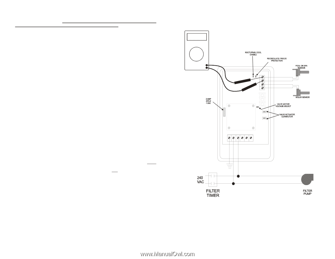
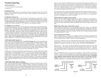
Freeze Protection If you are relying on the collectors naturally draining to provide freeze protection, it is very important that you use a non-positive seal valve or drill a hole (1/8"--1/4") in the diverter of a positive seal valve to allow the collectors to drain. Alternatively, the GL235 control can provide recirculate freeze protection. If enabled, when the GL-235 senses a freeze condition at the collector sensor, it will allow circulation of relatively warm water from the pool to the collector panels. The GL-235 will allow recirculation when the collector temperature falls below 40ºF and will stop circulation when the collector temperature rises above 42ºF. While this type of freeze protection has proven to be adequate in relatively mild climates, it is extremely important that the sensors be properly placed and that the homeowner realize that the system is unprotected in the event of a power failure. Recirculate freeze protection is NOT recommended in climates where freezing temperatures are common or last for extended periods. Hayward strongly recommends the use of GC-3 freeze snap switches if freeze protection is being utilized. Snap switches should be wired in series with the collector sensor. Placement of the snap switches at the coldest point of the collector array and exposed plumbing will help assure that freeze protection starts early enough to protect the system. The GL-235 is shipped from the factory with recirculate freeze protection disabled (the jumper is present but installed on one pin only). To activate recirculate freeze protection, install the jumper across both pins marked "RECIRC", located near the top right of the main circuit board. If recirculate freeze protection is to be used on a GL-235, either: • The filter pump must be set for continuous operation or • The GL235 High Voltage Output must be wired for Timer Override function. Nocturnal Cooling The GL-235 has nocturnal cooling logic, which can be enabled/disabled via a jumper on the main circuit board. During nighttime hours, when enabled, the GL-235 will circulate relatively warmer water from the pool to the collector panels, thus cooling the pool over time. The GL-235 will circulate water when the collector temperature AND the pool temperature is hotter than the high limit setting. Circulation will stop when the collector temperature is 3ºF less than the pool temperature OR the pool temperature is cooler than the high limit setting. The GL-235 is shipped from the factory with nocturnal cooling disabled (the jumper is present but installed on one pin only). To activate nocturnal cooling, install the jumper provided onto the two pins marked "COOLING" located near the top right of the main circuit board. If nocturnal cooling is to be used, either: • The filter pump must be set for continuous operation or • The GL235 High Voltage Output must be wired for Timer Override function. 4 Measuring Voltage of Pool Sensor (Use the same method to measure the Solar Sensor) Figure 5 9
-
 1
1 -
 2
2 -
 3
3 -
 4
4 -
 5
5 -
 6
6
 |
 |