Hayward CAT 6000 CAT 6000 Owners Manual - Page 6
Wall Mount Bracket
 |
View all Hayward CAT 6000 manuals
Add to My Manuals
Save this manual to your list of manuals |
Page 6 highlights
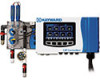
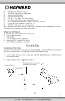
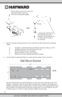
Remove three (3) screws to remove the wall mount bracket cover and Flow Cell counting plate together. Fig 2 Looking at the unit from the rear, slide the wall mount bracket to the left and pull out to remove from the back of the assembly. 3. Select a convenient mounting location for the controller unit which will meet the following criteria: A. Facilitates a combined (influent and effluent) maximum tubing run of 30'. B. Located a minimum of ten feet from pool or spa. C. GFI protected power source available. D. Easily accessible to pool or spa operator. E. Away from corrosive materials and physical hazards. 4. Securely attach the Mounting Plate to a vertical wall according to Figure 3a and 3b. Wall Mount Bracket 14.9" Fig 3a 4.6" Use the provided wall mount bracket template to locate screw holes where the unit is to be installed. A minimum of four (4) screws, two (2) at either end, is required. The location and hardware used must be able to support 35lbs, minimum. Ensure the mounting bracket is level when installing. The install location should have enough space to accommodate the unit and be within reach of a 110 Volt, 15 Amp (minimum) outlet to receive power. 5 USE ONLY HAYWARD GENUINE REPLACEMENT PARTS
-
 1
1 -
 2
2 -
 3
3 -
 4
4 -
 5
5 -
 6
6 -
 7
7 -
 8
8 -
 9
9 -
 10
10 -
 11
11 -
 12
12 -
13
-
14
-
15
-
16
-
17
-
18
-
19
-
20
-
21
-
22
-
23
-
24
-
25
-
26
-
27
-
28
-
29
-
30
-
31
-
32
-
33
-
34
-
35
-
36
-
37
-
38
-
39
-
40
-
41
-
42
-
43
-
44
-
45
-
46
-
47
-
48
 |
 |
