Hayward Electric Spa Heater Spa Heaters - Page 3
Installation, start-up, operating, instructions, electric, heater
 |
View all Hayward Electric Spa Heater manuals
Add to My Manuals
Save this manual to your list of manuals |
Page 3 highlights
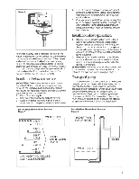
Installation, start-up and operating instructions for your electric spa heater Figure 2 Specifications and Dimensions: MODEL B.T.U. AMP WIRE BREAKER KW RATINGS SIZE* GROUND SIZE* GPH 240 240 WIRE 240 20° VOLT .VOLT SIZE* VOLT RISE GPH 40° WATER SHIP RISE CONN. WT. --- *1 61/4" 14-1 TOP --I1 112/ 4- " 6I 18" VIEW C-SPA-XI 5.5 18,766 5.5 23 10 10 30 120 56 112/ " 14 C-SPA-XI11 37,532 11 46 6 10 60 225 112 11/2" 14 1--- *PER NEC-LOCAL CODES APPLY-COPPER ONLY. WIRE SIZE APPLIES TO RUNS UP TO 50 FEET. FOR EACH ADDITIONAL 50 FOOT RUN, SELECT WIRE SIZE ONE GAUGE LARGER. FRONT 115/8" REAR p -f- 61/2" D__2_1/4L" Installer please note: 1. Inspect tor concealed damage upon receipt. Advise shipper of damage. File any damage claims with delivering carrier. 2. Spa heater must be installed according to instructions or manufacturer's warranty is void. 3. Your electric spa heater can be located anywhere in an outdoor or indoor location with a minimum clearance of six (6) inches to all combustible construction. Maintain adequate access clearance for servicing heater. Locate your heater in such a way that should the tank or any of its connections leak, the water will not damage anything. Under no circumstances will we, the manufacturer, be held liable for water damage in connection with your heater. The heater should be connected in the return line from the filter to the spa. Water shut off valves must not be installed in the piping from the outlet of the spa heater to the spa. Blocking the return pipe in any fashion can create a hazardous condition. Water piping: These heaters are designed for use with spa/ hot tub water only, as furnished by municipal water distribution systems. The warranty does not cover its use with mineral water, sea, salt or other nonpotable waters. *Minimum piping to be used is 1 1/2" I.D. (interior dimension). No valve or restriction is to be installed in line between heater outlet and spa unless the heater is below spa level. In that case, a swing check valve that does not include a shut-off feature or function should be installed to prevent back flow. No hartford loop is required. Optional CPVC use: CPVC piping may be used on both inlet and outlet threaded heater connections. Typical piping diagram: * No water shut off valves are to be installed between the heater outlet and the return to the spa/tub. Figure 3 SPA/TUB ELECTRIC SPA HEATER OUTLET INLET DRAIN VALVE BY-PASS UNIONS GATE VALVE (INLET ONLY) FILTER PUMP HAIR & LINT TRAP A G.E. silicone seal or similar sealant with a high elasticity must be used to compensate for temperature expansion and contraction of the dissimilar materials at the water connections, otherwise leakage will occur. Electrical connections: Before any electrical connections are made, be sure that the heater is full of water and that any valve in the cold water supply line is open. Check the rating plate and wiring diagram before proceeding. ANOTE: Customer to furnish disconnect switch. Wire in accordance with attached wiring diagrams. Field wiring, power supply conductors and branch circuit protectors must be installed by a qualified electrician in accordance with Article 680 of the National Electrical Code ANS/NFPA No. 70- 3
-
 1
1 -
 2
2 -
 3
3 -
 4
4 -
 5
5 -
 6
6 -
 7
7 -
 8
8
 |
 |
