Hayward GVA-24 Valve Actuator GVA-24-Valve-Actuator-Installation-Manual-092051 - Page 3
Introduction, Installation - how to install valve actuator
 |
View all Hayward GVA-24 Valve Actuator manuals
Add to My Manuals
Save this manual to your list of manuals |
Page 3 highlights
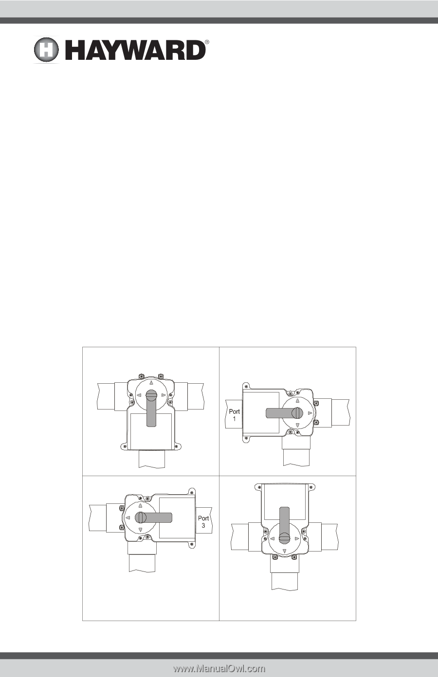
Introduction Description The GVA-24 Hayward Valve Actuator rotates 2-port and 3-port valves automatically. Use it with the Pro/Aqua Logic system or GL-235 Solar Controller to automate pool/spa operation, solar heating, cleaner operation, water features, or a variety of other uses. The industry standard configuration of the GVA-24 means that it is compatible with all major manufacturer's valves and pool automation systems. The unique cam setting feature ensures a quick and easy installation with the precise control of water flow. Installation Mounting Options Three Port Valve The Model GVA-24 Actuator may be mounted to the valve in four different positions (see below). Depending on the location of the common port (where water enters valve) and exit port (where water leaves valve), the cam settings may have to be changed. See diagrams/tables on the following pages to determine which configuration matches your system. A (Standard) B Port Port 1 3 Port 3 Port Port 2 2 Port 1 Port 2 C Port Port 1 3 Port 2 D 2 USE ONLY HAYWARD GENUINE REPLACEMENT PARTS
-
 1
1 -
 2
2 -
 3
3 -
 4
4 -
 5
5 -
 6
6 -
 7
7 -
 8
8
 |
 |