Hayward GVA-24 Valve Actuator GVA-24-Valve-Actuator-Installation-Manual-092051 - Page 5
Cam Adjustment, Synchronization Instruction, Manual Override - what does a valve actuator do
 |
View all Hayward GVA-24 Valve Actuator manuals
Add to My Manuals
Save this manual to your list of manuals |
Page 5 highlights
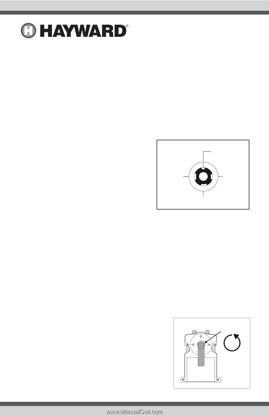
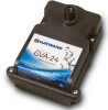
5. Use four (4) ¼-14x1½" long screws (packaged with the actuator) to secure it in place. Do not overtighten - be careful if using a power screwdriver. 6. Place valve handle on actuator shaft and tighten Locking Knob. Cam Adjustment 1. When changing the cam settings, move toggle switch at bottom of actuator to the OFF (cen- ter) position. 2. Unscrew and remove Locking Knob and handle from actuator shaft. 3. Remove the four (4) screws which hold the actuator cover on and remove cover. 4. The upper and lower cam are located on the actuator shaft. Slide the cams off the shaft splines and rotate to the desired position. Refer to the charts on the previous pages to determine the correct cam setting for your installation. Some installations may require settings not found on the chart (partial open, partial close, etc.) All settings are referenced from the small slot on the shaft, which is always 12 o'clock (see below). The upper cam effects the clockwise position stop point. The lower cam to effects the counterclockwise rotation stop point. 9 o'clock 12 o'clock (small slot) 3 o'clock 6 o'clock 5. The toggle switch on the bottom of the valve actuator can be used to verify if the new adjustment is correct (flip between ON1 and ON2). 6. Replace cover and handle and tighten screws and Locking Knob. 7. Put toggle switch back to ON1 or ON2 position. Synchronization Instruction After installation of the actuator(s), they may need to be synchronized. Out of synchronization refers to the condition where one actuator is rotating incorrectly in relation to another actuator. To correct this, simply flip the toggle switch at the bottom of the actuator which is out of synchroniza- tion between the ON1 and ON2 position. Manual Override In the event of a power failure, you may need to move the valve position manually. Before performing this procedure, turn off pool filtration just in case power resumes. Follow the instructions below for manual override of the GVA-24 actuator. Locking Knob 1. Put the toggle switch in the OFF (center) position. 4X 2. Unscrew the Locking Knob above the handle approximately 4 full turns (see below). 4 USE ONLY HAYWARD GENUINE REPLACEMENT PARTS
-
 1
1 -
 2
2 -
 3
3 -
 4
4 -
 5
5 -
 6
6 -
 7
7 -
 8
8
 |
 |