Hayward H150FDN All models English - Page 12
Model, Vent Diameter - installation
 |
View all Hayward H150FDN manuals
Add to My Manuals
Save this manual to your list of manuals |
Page 12 highlights
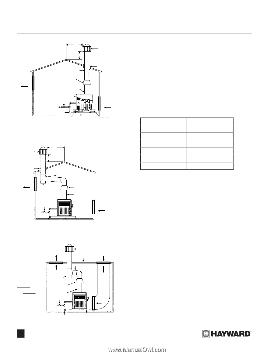
SECTION 3. INSTALLATION 10' VENT CAP INDOOR MODELS TYPICAL INSTALLATION 2' VENTILATION AIR VENT PIPE DHI VENT BACKDRAFT DIVERTER MUST BE INSTALLED DIRECTLY ON HEATER DO NOT ALTER OR CUT NECK WATER CONNECTIONS DO NOT RESTRICT OR REDUCE PIPE SIZE GAS COCK GAS SUPPLY SEE CHART FOR SIZE SEDIMENT TRAP DOUBLE WALL VENT PIPE THRU APPROVED ROOF JACK COMBUSTION AIR CHECK VALVE LEVEL PLASTIC PIPE (OPTIONAL) NON-COMBUSTIBLE (PVC, ETC.) FLOORING OR SLAB Figure 16: Vent Top Installation VENT CAP DOUBLE WALL VENT PIPE THRU APPROVED ROOF JACK 10' 2' GRADUAL RISE OF ONE INCH PER FOOT VENTILATION AIR DRIP TEE DHI VENT BACKDRAFT DIVERTER DO NOT ALTER OR CUT NECK GAS COCK COMBUSTION AIR SEDIMENT TRAP LEVEL NON-COMBUSTIBLE FLOORING OR SLAB Figure 17: Indoor Installation VENTILATION AIR VENT CAP COMBUSTION GROUND LEVEL AIR AIR DUCT FROM GROUND TO BASE NATURAL GAS ONLY BELOW GROUND INSTALLATION GRILL SIZE FOUR SQUARE INCHES PER 1000 BTUH FOR EACH GRILLE OUTLET DRIP TEE DHI VENT BACKDRAFT DIVERTER DO NOT ALTER OR CUT NECK GAS COCK RISE OF ONE INCH PER FOOT INLET SEDIMENT TRAP LEVEL NON-COMBUSTIBLE FLOORING OR SLAB Figure 18: Below Ground Installation 10 Venting: Locate the pool/spa heater as close as practical to a chimney or gas vent. See Figures 16,17 and 18. Do not alter back draft diverter (DHI) in any way. Install draft diverter (DHI) on top of heater. Vent material should be of blued steel or galvanized steel with double wall construction when passing through walls or a ceiling. Vent size diameters for the H-Series heaters are as per Figure 19. Vent Size Diameters Model H150 H200 H250 H300 H350 H400 Vent Diameter 6" 7" 7" 8" 9" 9" Figure 19 The discharge opening of the vent must be at least three feet above the roof surface and at least two feet higher than any portion of a building within ten feet horizontally. The vent stack shall be at least five feet in height above the drafthood outlet. The vent cap location shall have a minimum clearance of 4 feet horizontally from electric meters, gas meters, regulators and relief openings. The weight of the vent or chimney must not rest on the heater drafthood. Support must be provided in accordance with the applicable codes. The DHI drafthood must be easily removable for maintenance and inspection. The vent pipe must be supported to maintain proper clearances from combustibles. Venting extending above the roof by more than five feet should be guyed or braced above or below the roof to protect the vent from wind and/or snow damage.
-
 1
1 -
2
-
3
-
4
-
5
-
6
-
 7
7 -
 8
8 -
 9
9 -
 10
10 -
 11
11 -
 12
12 -
 13
13 -
 14
14 -
 15
15 -
 16
16 -
 17
17 -
18
-
19
-
20
-
21
-
22
-
23
-
24
-
25
-
26
-
27
-
28
-
29
-
30
-
31
-
32
-
33
-
34
-
35
-
36
-
37
-
38
-
39
-
40
-
41
-
42
-
43
-
44
-
45
-
46
-
47
-
48
-
49
-
50
-
51
-
52
 |
 |