Hayward Salt & Swim Salt & Swim Installation Quick Start Guide - Page 1
Hayward Salt & Swim Manual
 |
View all Hayward Salt & Swim manuals
Add to My Manuals
Save this manual to your list of manuals |
Page 1 highlights
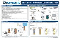
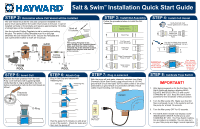
Salt & SwimTM Installation Quick Start Guide Before you begin Pre-Installation Checklist Pool is less than 25,000 gallons There is at least 10 inches of straight pipe in the return piping after all installed equipment (and the pipe is at least 2 inches off of the ground) to install the Cell Vessel The Control Box will be mounted within 3ft of a 120v GFCI outlet The Control Box will be mounted within 15ft of the installed Cell Vessel The Control Box will be installed at least 10 feet away from the pool. Pool plumbing is 1½" or 2" PVC (If black polyethylene pipe is used, see manual) You have a saw suitable for cutting PVC You have tools for mounting the Control Box (drill, drill bits, screwdriver) You have a permanent marker to mark the PVC pipe You have balanced your pool chemistry and have 3200ppm salt in your pool (see Chemistry Quickstart Guide) Installation Preparation Read this entire Quickstart Guide Remove power to filter pump Drain water from pool piping Verify that all parts are included in the box You are wearing safety glasses and have read the safety precautions in the owner's manual Overview Spread out parts on ground Cell Vessel Cutting Template 1½" Nut Assembly (2) Strap Wrench Grease Retaining Nut Control Box Mounting Template Screws Cell Cap & Cord Collar Compression Ring Gasket (2) 2" Nut Assembly (2) Cell Vessel Cell Control Box STEP 1: Mount Control Box Mount the Control Box to a wall or post within 3 feet of a GFCI outlet, making sure that the cord will reach. The Control Box will also have to be mounted within 15 feet of the Cell Vessel as shown in the Overview. Use the included Mounting Template to help locate the mounting holes and fasten the Control Box to the intended surface. WWW.HAYWARD.COM 855-429-9274 Turn Over
-
 1
1 -
 2
2
 |
 |
