Hayward Star-Clear™ Plus Model: ALL MODELS - Page 4
Reinstalling Cartridge Element - star clear plus c1200 manual
 |
View all Hayward Star-Clear™ Plus manuals
Add to My Manuals
Save this manual to your list of manuals |
Page 4 highlights
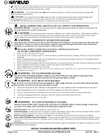
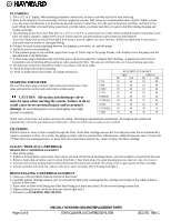
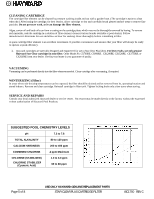
PLUMBING 1. Use 1-1/2" or 2" piping. When making permanent connections, be sure to provide unions for easy servicing. 2. Refer to the diagrams on previous page for basic suggested valving. Ball valves are recommended where needed. While systems vary, the main consideration is to provide the desired control of water flow from the pool to the pump and filter, and back to the pool. When the filter is located below water level, provide valves to prevent back flow of water to the filter during cleaning and routine servicing. 3. All plumbing on the Star-Clear Plus filter is 1-1/2" or 2" N.P.T. or socket (solvent weld). When making threaded connections to the filter use plastic adapters. Apply three turns of Teflon tape (or use special plastic pipe sealant) to male threads. Screw the fitting into the thread hand tight; then using a wrench, tighten one more full turn. Additional tightening is unnecessary and could result in broken or damaged fittings. 4. Connect the pool suction plumbing between the skimmer, pool outlet, etc. and the pump. 5. Install the pool return plumbing. 6. If the pressure gauge is not installed, apply three wraps of Teflon tape to the gauge threads, and carefully screw the gauge into the threaded hole in the filter head. 7. A filter drain plug is furnished with each filter and is all that is needed for complete filter draining. A manual air relief valve is furnished to aid in bleeding off unwanted air when starting the filter. The auto air relief provides air removal during operation. 8. All electrical connections should be made in accordance with local codes. 9. Check for joint leaks before operating 10. Refer to pump instruction booklet for pump information. REQUIRED CLEARANCE SIDE ABOVE IN CM IN CM STARTING THE FILTER Be sure filter drain plug is closed. Open manual air relief valve a few turns and open the suction and return valves (when used). C751 C900 C1200 18 46 19 48 18 46 19 48 18 46 25 64 C7512 18 46 19 48 CAUTION: All suction and discharge valves C9002(S) 18 46 19 48 must be open when starting the system. Failure to do so C12002(S) 18 46 25 64 could cause severe personal injury and/or property C1502 18 46 25 64 damage. Be sure locking knob is secure (hand tighten-only slight C17502(S) 18 46 30 76 pressure is required). C2002 18 46 30 76 Stand clear of the filter and prime and start the pump, following the manufacturer's instructions. Air trapped in the system will automatically vent to the pool and out air relief valve. Close air relief valve as soon as air is vented. FILTERING Filtration starts as soon as flow is steady through the filter. As the filter cartridge removes dirt from the pool water, the accumulated dirt causes a resistance to flow. As a result, the gauge pressure will rise and the flow will decrease. When the pressure rises 7-10 psi (.49.70 Bar) above the starting pressure, or when flow decreases below desired rate, clean or replace the filter cartridge. CLEAN / REPLACE CARTRIDGE REMOVING CARTRIDGE ELEMENT 1. Shut off the pump. 2. If filter is located below water level, close valves or block off suction & discharge lines to prevent backflow of water from the pool. 3. Remove drain plug and allow water to drain from filter. Close drain plug. (To assist draining process; open air vent a few turns.) 4. Unscrew and remove locking knob (counterclockwise direction) and carefully lift off top cover to gain access to filter cartridge. 5. Lift out cartridge and clean. Or, replace with clean, spare cartridge. (See Cleaning Cartridge.) REINSTALLING CARTRIDGE ELEMENT 1. Clean any collected debris from the bottom of filter body. 2. Carefully replace cartridge element over tie rod and into filter body ensuring that the cartridge sits evenly on the collector hub in bottom of filter body. 3. Place cover on filter body (being sure filter head 0-ring is in place and clean). Fit tie rod end through center hole. 4. Tighten locking knob in clockwise direction. (Hand tight only.) 5. Proceed as in STARTING THE FILTER. Page 4 of 8 USE ONLY HAYWARD GENUINE REPLACEMENT PARTS STAR-CLEAR PLUS CARTRIDGE FILTER ISC1750 REV C
-
 1
1 -
 2
2 -
 3
3 -
 4
4 -
 5
5 -
 6
6 -
 7
7 -
 8
8
 |
 |