HealthRider 875 P Instruction Manual - Page 7
Unplug The Power Cord
 |
View all HealthRider 875 P manuals
Add to My Manuals
Save this manual to your list of manuals |
Page 7 highlights
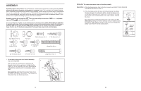
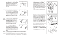
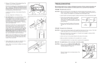
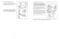
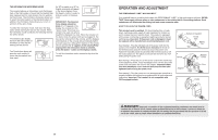
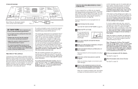
Locate the Reed Switch (18) and the Magnet (101) on the left side of the Pulley (78). Turn the Pulley until the Magnet is aligned with the Reed Switch. Make sure 1/8" that the gap between the Magnet and the Reed 24 78 Switch is about 1/8". If necessary, loosen the Screw 18 101 (24), move the Reed Switch slightly, and then retighten the Screw. Reattach the hood, and run the treadmill for a few minutes to check for a correct speed reading. Top View PROBLEM: The walking belt slows when walked on SOLUTION: a. Use only a single-outlet surge suppressor that meets all of the specifications described on page 11. b. If the walking belt is overtightened, treadmill performance may decrease and the walking belt may become damaged. Remove the key and UNPLUG THE POWER CORD. Using the hex key, turn both rear roller adjustment bolts counterclockwise, 1/4 of a turn. When the walking belt is properly tightened, you should be able to lift each side of the walking belt 3 to 4 inches off the walking platform. Be careful to keep the walking belt centred. Plug in the power cord, insert the key, and run the treadmill for a few minutes. Repeat until the walking belt is properly tightened. b 3"-4" Rear Roller Adjustment Bolts c. If the walking belt still slows when walked on, please call our Customer Service Department. PROBLEM: The walking belt is off-centre or slips when walked on SOLUTION: a. If the walking belt is off-centre, first remove the key and UNPLUG THE POWER CORD. If the walking a belt has shifted to the left, use the hex key to turn the left rear roller bolt clockwise 1/2 of a turn; if the walking belt has shifted to the right, turn the bolt counterclockwise 1/2 of a turn. Be careful not to over- tighten the walking belt. Plug in the power cord, insert the key, and run the treadmill for a few minutes. Repeat until the walking belt is centred. b. If the walking belt slips when walked on, first remove the key and UNPLUG THE POWER CORD. Using b the hex key, turn both rear roller bolts clockwise, 1/4 of a turn. When the walking belt is correctly tightened, you should be able to lift each side of the walking belt 3 to 4 inches off the walking platform. Be careful to keep the walking belt centred. Plug in the power cord, insert the key, and carefully walk on the treadmill for a few minutes. Repeat until the walking belt is properly tightened. PROBLEM: The incline of the treadmill does not change correctly or does not change when iFIT.com CDs and videos are played SOLUTION: a. With the key inserted in the console, press one of the Incline buttons. Whilst the incline is changing, remove the key. After a few seconds, reinsert the key. The treadmill will automatically rise to the maximum incline level and then return to the minimum level. This will recalibrate the incline. 26 2. Identify the Right and Left Uprights (55, 64); the Left Upright has two small holes near the square post. Hold the Right Upright (55) near the Base (116), and orient the Right Upright as shown. Make sure that the Right Upright bends in the direction shown. Straighten the Wire Harness (49), and feed it into the lower end of the Right Upright and out of the upper end. Make sure that the Wire harness is not pinched. Hand tighten two Upright Bolts (112) with Star Washers (111) into the bottom of the Base (116) and the lower end of the Right Upright. Attach the Left Upright (64) as described above. Note: There is not a wire harness on the left side. 2 112 111 49 116 Holes 55 Bend 64 112 111 3. With the help of a second person, carefully tip the treadmill back down so that the Uprights (55, 64 [not shown]) are vertical. Make sure that the end of the Wire Harness (49) does not fall into the Right Upright. Set the Console Base (38) on the Right Upright (55) as shown. Check the pins in the connector on the Wire Harness and make sure that they are straight. Connect the Wire Harness to the indicated connector on the back of the Console Base. Make sure to insert the connectors properly (see the inset drawing). The connectors should slide together easily and snap into place. If the connectors do not slide together easily and snap into place, turn one connector and try again. Insert the included plastic tie through the small hole in the Right Upright (55) and around the Wire Harness (49) as shown. Connect the two indicated ground wires. 3 38 Tie 55 49 Ground Wires 49 4. Open parts bag 4-5. Loosely thread a 1/2" Tek Screw (113) into the left side of the Crossbar (46) and the Left Upright (64). Note: The Tek Screw may be preassembled in the Left Upright. Attach the Latch Assembly (32) to the Left Upright (64) with two 3/4" Tek Screws (35). 4 113 (Leave loose) 46 35 32 64 7
-
 1
1 -
 2
2 -
 3
3 -
 4
4 -
 5
5 -
 6
6 -
 7
7 -
 8
8 -
 9
9 -
 10
10 -
 11
11 -
 12
12 -
13
-
14
-
15
-
16
-
17
-
18
 |
 |
