HealthRider C865e Elliptical English Manual - Page 8
Make sure that the Upper Body Arms
 |
View all HealthRider C865e Elliptical manuals
Add to My Manuals
Save this manual to your list of manuals |
Page 8 highlights
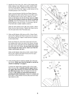
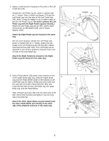
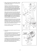
7. Apply a small amount of the included Teflon® lubricant to a paper towel. Rub a thin film of the lubricant onto each Upper Body Leg (31). Identify the Left Upper Body Arm (107), which is marked with a sticker. Slide the Left Upper Body Arm onto the left Upper Body Leg (31). Slide the Right Upper Body Arm (85) onto the right Upper Body Leg (not shown). Make sure that the Upper Body Arms are on the correct sides. Next, slide an Axle Cover (26) onto the post on each Upper Body Arm. Apply a generous amount of the included grease to the Arm Axle (19). Insert the Arm Axle into the Upright (2), the right Axle Cover (26), and the Right Upper Body Arm (85). Next, push the Arm Axle into the Upright until the left end of the Arm Axle is flush with the left side of the Upright. Then, raise the Left Upper Body Arm (107), and insert the Arm Axle into the left Axle Cover (26) and the Left Upper Body Arm. Using the included pedal tool, tap two Push Nuts (24) about 1/8" onto each end of the Arm Axle (19). Make sure that the Push Nuts are turned as shown in the inset drawing. Note: It may be helpful if another person holds a block of wood against one end of the Arm Axle while you tap Push Nuts onto the other end. Press the small tabs on the Upper Body Arm Caps (91) into the two Axle Covers (26). 7 85 2 91 107 19 26 91 24 Grease Tube 31 24 26 Lubricate Pedal Tool 24 19 8. Have another person hold the Console (17) near the Upright (2). Connect the Upper Wire Harness (95) to the wire harness on the Console (17). Connect the Pulse Extension Wire (101) to the pulse wire on the Console. Next, locate the two ground wires that are attached to the Upright (2). Connect the ground wires to the two smallest wires on the Console. Carefully insert all excess wiring up into the Console (17) and down into the Upright (2). Attach the Console to the Upright with four M4 x 16mm Screws (98). (Note: The Screws may be found in the console box.) Be careful to avoid pinching the wires. 8 17 Do not pinch the wires during this step. 101 98 95 Ground 98 Wires 2 8
-
 1
1 -
2
-
 3
3 -
 4
4 -
 5
5 -
 6
6 -
 7
7 -
 8
8 -
 9
9 -
 10
10 -
 11
11 -
 12
12 -
 13
13 -
14
-
15
-
16
-
17
-
18
-
19
-
20
-
21
-
22
-
23
-
24
-
25
-
26
-
27
-
28
 |
 |
