HP 100eu Maintenance and Service Guide - Compaq 100eu Small Form Factor, 100 e - Page 144
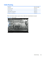
Make sure all cables are correctly routed when reassembling the computer. See
 |
View all HP 100eu manuals
Add to My Manuals
Save this manual to your list of manuals |
Page 144 highlights
● 3 on the right side ● 2 on the left side Figure 8-29 Display panel tabs 11. Pull back on each clip to disengage the clip from the display enclosure. Figure 8-30 Loosening display panel tabs 12. Lift the display panel from the enclosure. To install a display panel, reverse the removal procedures. Make sure all cables are correctly routed when reassembling the computer. See Cable Routing on page 135 for an image that shows how to correctly route the cables. 134 Chapter 8 Removal and Replacement Procedures All-in One (AIO) Chassis
-
 1
1 -
2
-
3
-
4
-
5
-
6
-
7
-
8
-
9
-
10
-
11
-
12
-
13
-
14
-
15
-
16
-
17
-
18
-
19
-
20
-
21
-
22
-
23
-
24
-
25
-
26
-
27
-
28
-
29
-
30
-
31
-
32
-
33
-
34
-
35
-
36
-
37
-
38
-
39
-
40
-
41
-
42
-
43
-
44
-
45
-
46
-
47
-
48
-
49
-
50
-
51
-
52
-
53
-
54
-
55
-
56
-
57
-
58
-
59
-
60
-
61
-
62
-
63
-
64
-
65
-
66
-
67
-
68
-
69
-
70
-
71
-
72
-
73
-
74
-
75
-
76
-
77
-
78
-
79
-
80
-
81
-
82
-
83
-
84
-
85
-
86
-
87
-
88
-
89
-
90
-
91
-
92
-
93
-
94
-
95
-
96
-
97
-
98
-
99
-
100
-
101
-
102
-
103
-
104
-
105
-
106
-
107
-
108
-
109
-
110
-
111
-
112
-
113
-
114
-
115
-
116
-
117
-
118
-
119
-
120
-
121
-
122
-
123
-
124
-
125
-
126
-
127
-
128
-
129
-
130
-
131
-
132
-
133
-
134
-
135
-
136
-
137
-
138
-
 139
139 -
 140
140 -
 141
141 -
 142
142 -
 143
143 -
 144
144 -
 145
145 -
 146
146 -
 147
147 -
 148
148 -
 149
149 -
150
-
151
-
152
-
153
-
154
-
155
-
156
-
157
-
158
-
159
-
160
-
161
-
162
-
163
-
164
-
165
-
166
-
167
-
168
-
169
-
170
-
171
-
172
-
173
-
174
-
175
-
176
-
177
-
178
-
179
-
180
-
181
-
182
-
183
-
184
-
185
-
186
-
187
-
188
-
189
-
190
-
191
-
192
-
193
-
194
-
195
-
196
-
197
-
198
-
199
-
200
-
201
-
202
-
203
-
204
-
205
-
206
-
207
-
208
-
209
-
210
-
211
-
212
-
213
-
214
-
215
 |
 |
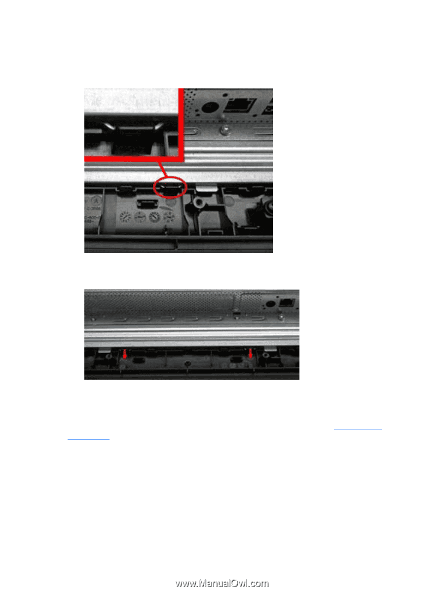
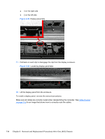
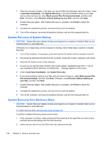
●
3 on the right side
●
2 on the left side
Figure 8-29
Display panel tabs
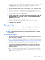
11.
Pull back on each clip to disengage the clip from the display enclosure.
Figure 8-30
Loosening display panel tabs
12.
Lift the display panel from the enclosure.
To install a display panel, reverse the removal procedures.
Make sure all cables are correctly routed when reassembling the computer. See
Cable Routing
on page
135
for an image that shows how to correctly route the cables.
134
Chapter 8
Removal and Replacement Procedures All-in One (AIO) Chassis