HP 1220c Support Guide - Page 118
Left Hand Side, Right Hand Side, System Level Block Diagram Electrical, Logic Board Signal Flow - drivers
 |
View all HP 1220c manuals
Add to My Manuals
Save this manual to your list of manuals |
Page 118 highlights
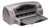
SYSTEM LEVEL BLOCK DIAGRAM (ELECTRICAL) LOGIC BOARD SIGNAL FLOW USB Connector USB Interface IEEE 1284 Interface BDM Connector ACLK ASID ASOD ALOAD Reset Top Door Sensor Arabian Analog ASIC +5V Output Supply +3.3V Output Supply +18V Input Supply Centronic Connector To Personal Computer USB/Centronic Connector Flash 2x1Mx16 ROM_Addr[1:21] ROM_DATA[0:15] ROM_CONTROL[0:3] Helios C Digital ASIC EEClk EEData EEPROM 1024 x 8 Bytes BDM Interface Signals SDRAM_Addr[0:13] SDRAM_DATA[0:15] SDRAM_CONTROL[0:8] XI XO Escher Logic Board GPIO Assignment 0 KP_Cancel Button 1 USB_Enable 2 HumidFast 3 BackDoorSensor 4 PwrLED 5 MagicLED 6 InkLED 7 KP_MagicButton 8 PwrButton 9 TopDoorSensor 10 PaperSensor 11 PSM_nEnable 12 PwrOn 13 RampMotorEnable 14 IndexMaker 15 Mechless Back Door Sensor SDRAM 1x4Mx16 Key Panel x2 Power x7 Magic Power ON/OFF Signal Flow (1) User press Power Button on Key Panel (2) Power Supply Module (PSM) activate "PSM_nEnable" (3) Escher Logic Board activate/deactivate "PSM_On" to turn ON/OFF PSM. Ink Cancel Service Station (LEFT HAND SIDE) 15.975MHz Crystal Oop Sensor x5 Line Feed Motor Driver Output Ramp Motor Driver Dudley III ASIC Interface Signals Trident+ ASIC Interface Signals 24 Ways Flex connected to Carriage Board Connector connector 24 Ways Flex Power +32V Input Supply (A) (B) (C) PSM_nEnable PSM_On 30 Ways connector (A) To Service Station Motor & Fan (B) To Line Feed Motor (C) To Output Ramp Motor (2) (3) (1) +18V/+32V from Power Supply Module To Power Supply Module - Power Switch Status Sense Power Supply Moule x2 x5 x2 x2 Output Ramp Motor Line Feed Board Line Feed Motor (RIGHT HAND SIDE) Carriage Motor Lee Chin Kang 29 September 1999 RevA
-
 1
1 -
2
-
3
-
4
-
5
-
6
-
7
-
8
-
9
-
10
-
11
-
12
-
13
-
14
-
15
-
16
-
17
-
18
-
19
-
20
-
21
-
22
-
23
-
24
-
25
-
26
-
27
-
28
-
29
-
30
-
31
-
32
-
33
-
34
-
35
-
36
-
37
-
38
-
39
-
40
-
41
-
42
-
43
-
44
-
45
-
46
-
47
-
48
-
49
-
50
-
51
-
52
-
53
-
54
-
55
-
56
-
57
-
58
-
59
-
60
-
61
-
62
-
63
-
64
-
65
-
66
-
67
-
68
-
69
-
70
-
71
-
72
-
73
-
74
-
75
-
76
-
77
-
78
-
79
-
80
-
81
-
82
-
83
-
84
-
85
-
86
-
87
-
88
-
89
-
90
-
91
-
92
-
93
-
94
-
95
-
96
-
97
-
98
-
99
-
100
-
101
-
102
-
103
-
104
-
105
-
106
-
107
-
108
-
109
-
110
-
111
-
112
-
 113
113 -
 114
114 -
 115
115 -
 116
116 -
 117
117 -
 118
118 -
 119
119 -
 120
120 -
 121
121 -
 122
122 -
 123
123 -
124
-
125
-
126
-
127
-
128
-
129
-
130
-
131
-
132
-
133
-
134
-
135
-
136
-
137
-
138
-
139
-
140
-
141
-
142
-
143
-
144
-
145
-
146
-
147
-
148
-
149
-
150
-
151
-
152
-
153
-
154
-
155
-
156
-
157
-
158
-
159
-
160
-
161
-
162
-
163
-
164
-
165
-
166
-
167
-
168
-
169
-
170
-
171
-
172
-
173
-
174
-
175
-
176
-
177
-
178
-
179
-
180
-
181
-
182
-
183
-
184
-
185
-
186
-
187
-
188
-
189
-
190
-
191
-
192
-
193
-
194
-
195
-
196
-
197
-
198
-
199
-
200
-
201
-
202
-
203
-
204
-
205
-
206
-
207
-
208
-
209
-
210
-
211
-
212
-
213
-
214
-
215
-
216
-
217
-
218
-
219
-
220
-
221
-
222
-
223
-
224
-
225
-
226
-
227
-
228
-
229
-
230
-
231
 |
 |
