HP 15-bn000 Maintenance and Service Guide - Page 88
from the module., Disconnect the cable
 |
View all HP 15-bn000 manuals
Add to My Manuals
Save this manual to your list of manuals |
Page 88 highlights
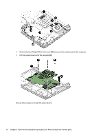
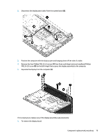
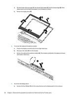
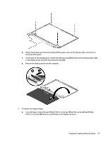
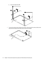
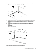
a. Flex the inside of the top edge (1), the left and right edges (2), and the bottom edge (3) of the display bezel until the bezel disengages from the display enclosure. b. Remove the display bezel (4). 2. To remove the webcam/microphone module: a. Position the display assembly with the top edge toward you. b. Disconnect the cable (1) from the module. c. Remove the webcam/microphone module (2). (The module is attached to the display enclosure with double-sided tape.) 3. To remove the display panel: a. Remove the four Phillips PM2.0×3.0 screws that secure the display panel to the enclosure. 80 Chapter 6 Removal and replacement procedures for Authorized Service Provider parts
-
 1
1 -
2
-
3
-
4
-
5
-
6
-
7
-
8
-
9
-
10
-
11
-
12
-
13
-
14
-
15
-
16
-
17
-
18
-
19
-
20
-
21
-
22
-
23
-
24
-
25
-
26
-
27
-
28
-
29
-
30
-
31
-
32
-
33
-
34
-
35
-
36
-
37
-
38
-
39
-
40
-
41
-
42
-
43
-
44
-
45
-
46
-
47
-
48
-
49
-
50
-
51
-
52
-
53
-
54
-
55
-
56
-
57
-
58
-
59
-
60
-
61
-
62
-
63
-
64
-
65
-
66
-
67
-
68
-
69
-
70
-
71
-
72
-
73
-
74
-
75
-
76
-
77
-
78
-
79
-
80
-
81
-
82
-
 83
83 -
 84
84 -
 85
85 -
 86
86 -
 87
87 -
 88
88 -
 89
89 -
 90
90 -
 91
91 -
 92
92 -
 93
93 -
94
-
95
-
96
-
97
-
98
-
99
-
100
-
101
-
102
-
103
-
104
-
105
-
106
-
107
-
108
-
109
-
110
-
111
-
112
-
113
-
114
-
115
-
116
-
117
-
118
-
119
-
120
-
121
-
122
-
123
-
124
-
125
-
126
-
127
-
128
-
129
-
130
-
131
-
132
-
133
-
134
-
135
-
136
-
137
-
138
 |
 |
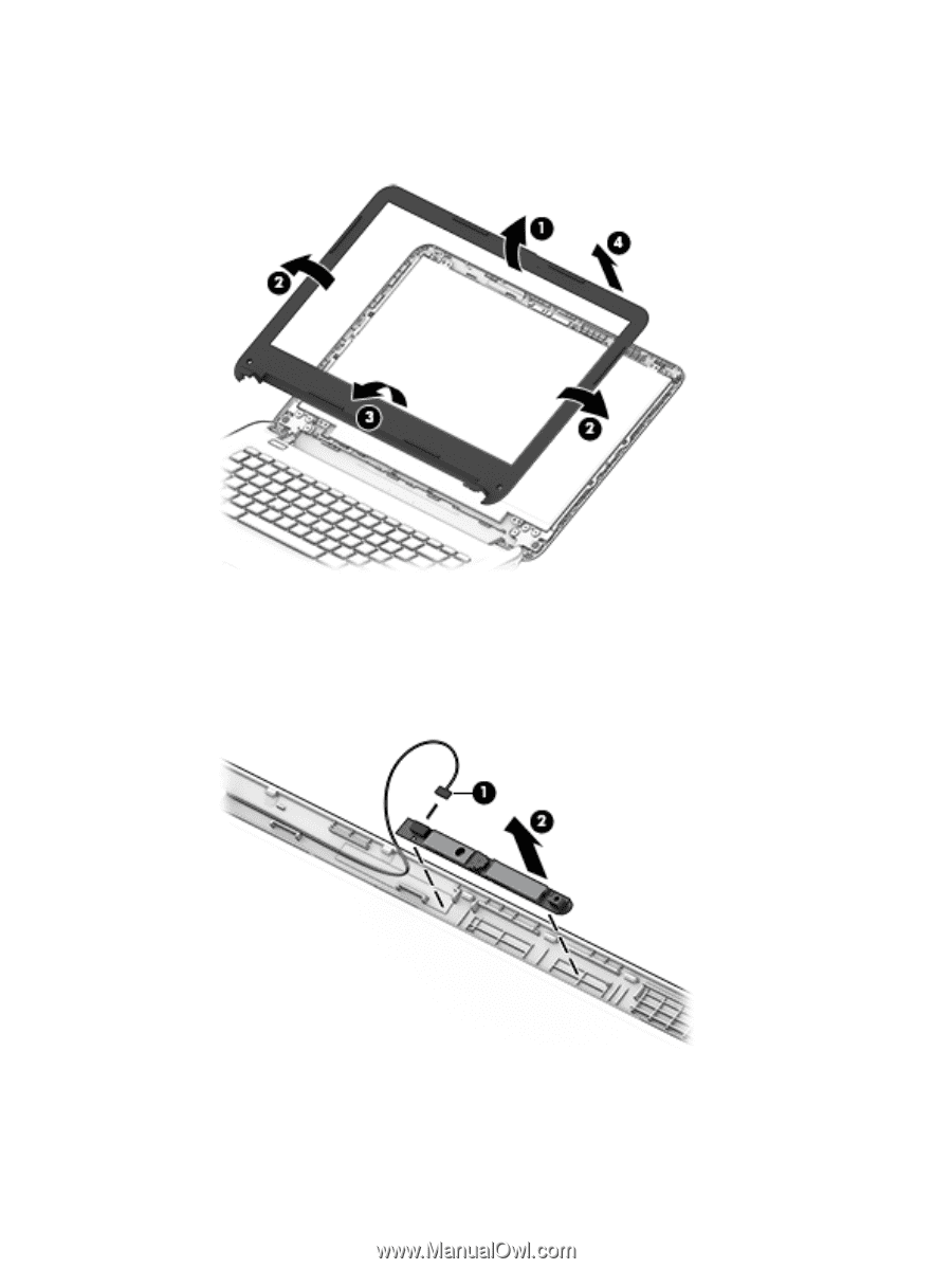
a.
Flex the inside of the top edge
(1)
, the left and right edges
(2)
, and the bottom edge
(3)
of the
display bezel until the bezel disengages from the display enclosure.
b.
Remove the display bezel
(4)
.
2.
To remove the webcam/microphone module:
a.
Position the display assembly with the top edge toward you.
b.
Disconnect the cable
(1)
from the module.
c.
Remove the webcam/microphone module
(2)
. (The module is attached to the display enclosure
with double-sided tape.)
3.
To remove the display panel:
a.
Remove the four Phillips PM2.0×3.0 screws that secure the display panel to the enclosure.
80
Chapter 6
Removal and replacement procedures for Authorized Service Provider parts