HP 15-f010dx HP 15 Notebook PC Maintenance and Service Guide - Page 67
Remove the system board by sliding it up and to the, Carefully remove from the power connector
 |
View all HP 15-f010dx manuals
Add to My Manuals
Save this manual to your list of manuals |
Page 67 highlights
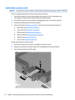
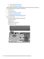
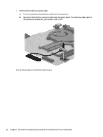
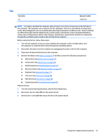
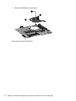
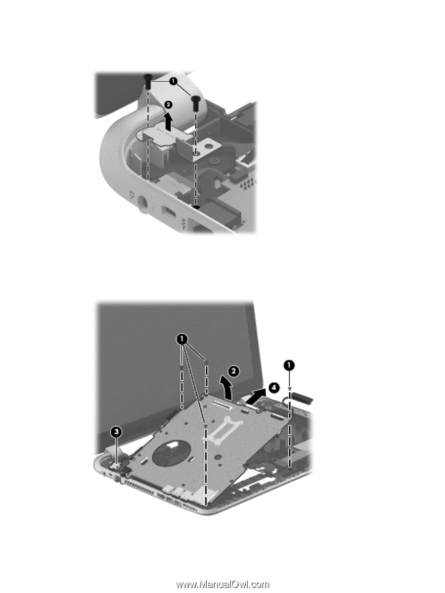
2. Remove the two Phillips M2.5×6.5 and M2.0×5.0 screws (1). Remove the bracket (2) that secures the power connector bracket to the base enclosure. 3. Remove the four Phillips M2.5×5.0 screws (1) that secure the system board to the base enclosure. 4. Lift the right side of the system board (2) until it rests at an angle. 5. Carefully remove from the power connector (3). Remove the system board by sliding it up and to the right at an angle and pull the system board (4) carefully to the right. Component replacement procedures 57
-
 1
1 -
2
-
3
-
4
-
5
-
6
-
7
-
8
-
9
-
10
-
11
-
12
-
13
-
14
-
15
-
16
-
17
-
18
-
19
-
20
-
21
-
22
-
23
-
24
-
25
-
26
-
27
-
28
-
29
-
30
-
31
-
32
-
33
-
34
-
35
-
36
-
37
-
38
-
39
-
40
-
41
-
42
-
43
-
44
-
45
-
46
-
47
-
48
-
49
-
50
-
51
-
52
-
53
-
54
-
55
-
56
-
57
-
58
-
59
-
60
-
61
-
 62
62 -
 63
63 -
 64
64 -
 65
65 -
 66
66 -
 67
67 -
 68
68 -
 69
69 -
 70
70 -
 71
71 -
 72
72 -
73
-
74
-
75
-
76
-
77
-
78
-
79
-
80
-
81
-
82
-
83
-
84
-
85
-
86
-
87
-
88
-
89
-
90
-
91
-
92
-
93
-
94
-
95
-
96
-
97
 |
 |
2.
Remove the two Phillips M2.5×6.5 and M2.0×5.0 screws
(1)
. Remove the bracket
(2)
that secures
the power connector bracket to the base enclosure.
3.
Remove the four Phillips M2.5×5.0 screws
(1)
that secure the system board to the base enclosure.
4.
Lift the right side of the system board
(2)
until it rests at an angle.
5.
Carefully remove from the power connector
(3)
. Remove the system board by sliding it up and to the
right at an angle and pull the system board
(4)
carefully to the right.
Component replacement procedures
57