HP 15-g060nr HP 15 Notebook PC Compaq 15 Notebook PC HP 250 G3 Notebook PC HP - Page 84
WLAN module see, Hard drive see
 |
View all HP 15-g060nr manuals
Add to My Manuals
Save this manual to your list of manuals |
Page 84 highlights
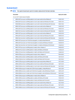
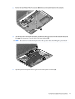
Description Spare part number ● Intel Core i3-4010U processor and 1 GB of discrete graphics memory in touch screen models with Windows 8 Standard 763752-501 ● Intel Core i3-4010U processor and 1 GB of discrete graphics memory in touch screen models with Windows 8 Professional 763752-601 ● Intel Core i3-4010U processor and UMA graphics memory in touch screen models without Windows 8 761536-001 and WWAN ● Intel Core i3-4010U processor and UMA graphics memory in models with Windows 8 Standard and WWAN 761536-501 ● Intel Core i3-4010U processor and UMA graphics memory in models with Windows 8 Professional and 761536-601 WWAN ● Intel Core i5-4210U processor and UMA graphics memory in models without Windows 8 and WWAN 761535-001 ● Intel i5-4210U processor and UMA graphics memory in models with Windows 8 Standard and WWAN 761535-501 ● Intel i5-4210U processor and UMA graphics memory in models with Windows 8 Professional and WWAN 761535-601 Before removing the system board, follow these steps: 1. Shut down the computer. If you are unsure whether the computer is off or in Hibernation, turn the computer on, and then shut it down through the operating system. 2. Disconnect all external devices connected to the computer. 3. Disconnect the power from the computer by first unplugging the power cord from the AC outlet and then unplugging the AC adapter from the computer. 4. Remove the battery (see Battery on page 49). 5. Remove the following components: ● Keyboard (see Keyboard on page 55) ● Top cover (see Top cover on page 58) ● WLAN module (see WLAN module on page 66) ● Hard drive (see Hard drive on page 64) NOTE: When replacing the system board, be sure that the following components are removed from the defective system board and installed on the replacement system board: ● Memory module (see Memory module on page 85) ● Heat sink assembly (see Heat sink assembly on page 81) To remove the system board: 1. Position the computer upright, and then disconnect the following cables from the system board: (1): Power connector cable (2): Speaker cable (3): Fan cable (4): Display cable 76 Chapter 4 Removal and replacement procedures
-
 1
1 -
2
-
3
-
4
-
5
-
6
-
7
-
8
-
9
-
10
-
11
-
12
-
13
-
14
-
15
-
16
-
17
-
18
-
19
-
20
-
21
-
22
-
23
-
24
-
25
-
26
-
27
-
28
-
29
-
30
-
31
-
32
-
33
-
34
-
35
-
36
-
37
-
38
-
39
-
40
-
41
-
42
-
43
-
44
-
45
-
46
-
47
-
48
-
49
-
50
-
51
-
52
-
53
-
54
-
55
-
56
-
57
-
58
-
59
-
60
-
61
-
62
-
63
-
64
-
65
-
66
-
67
-
68
-
69
-
70
-
71
-
72
-
73
-
74
-
75
-
76
-
77
-
78
-
 79
79 -
 80
80 -
 81
81 -
 82
82 -
 83
83 -
 84
84 -
 85
85 -
 86
86 -
 87
87 -
 88
88 -
 89
89 -
90
-
91
-
92
-
93
-
94
-
95
-
96
-
97
-
98
-
99
-
100
-
101
-
102
-
103
-
104
-
105
-
106
-
107
-
108
-
109
-
110
-
111
-
112
-
113
-
114
-
115
-
116
-
117
-
118
-
119
-
120
-
121
-
122
-
123
-
124
-
125
-
126
-
127
-
128
-
129
-
130
-
131
-
132
-
133
-
134
-
135
-
136
-
137
-
138
-
139
-
140
-
141
-
142
-
143
-
144
-
145
-
146
-
147
-
148
 |
 |