HP 2000-bf69WM HP 2000 Notebook PC Compaq Presario CQ58 Notebook PC Maintenanc - Page 45
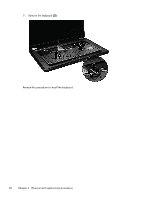
Memory module, by pulling it away from the slot at an angle. - memory slots
 |
View all HP 2000-bf69WM manuals
Add to My Manuals
Save this manual to your list of manuals |
Page 45 highlights
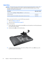
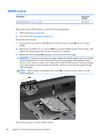
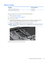
Memory module Description 4 GB PC3 12800 16000 MHz shared 2 GB PC3 12800 16000 MHz shared Spare part number 641369-001 652972-001 Before removing the memory module, remove the following components: 1. Battery (see Battery on page 30) 2. Service door (see Service door on page 31) Remove the memory module: 1. Spread the retaining tabs (1) on each side of the memory module slot to release the memory module. (The edge of the module opposite the slot rises away from the computer.) 2. Remove the module (2) by pulling it away from the slot at an angle. NOTE: Memory modules are designed with a notch (3) to prevent incorrect insertion into the memory module slot. Reverse this procedure to install a memory module. Component replacement procedures 37
-
 1
1 -
2
-
3
-
4
-
5
-
6
-
7
-
8
-
9
-
10
-
11
-
12
-
13
-
14
-
15
-
16
-
17
-
18
-
19
-
20
-
21
-
22
-
23
-
24
-
25
-
26
-
27
-
28
-
29
-
30
-
31
-
32
-
33
-
34
-
35
-
36
-
37
-
38
-
39
-
 40
40 -
 41
41 -
 42
42 -
 43
43 -
 44
44 -
 45
45 -
 46
46 -
 47
47 -
 48
48 -
 49
49 -
 50
50 -
51
-
52
-
53
-
54
-
55
-
56
-
57
-
58
-
59
-
60
-
61
-
62
-
63
-
64
-
65
-
66
-
67
-
68
-
69
-
70
-
71
-
72
-
73
-
74
-
75
-
76
-
77
-
78
-
79
-
80
-
81
-
82
-
83
-
84
-
85
-
86
-
87
-
88
-
89
-
90
-
91
-
92
-
93
-
94
 |
 |

Memory module
Description
Spare part number
4 GB PC3 12800 16000 MHz shared
641369-001
2 GB PC3 12800 16000 MHz shared
652972-001
Before removing the memory module, remove the following components:
1.
Battery (see
Battery
on page
30
)
2.
Service door (see
Service door
on page
31
)
Remove the memory module:
1.
Spread the retaining tabs
(1)
on each side of the memory module slot to release the memory
module. (The edge of the module opposite the slot rises away from the computer.)
2.
Remove the module
(2)
by pulling it away from the slot at an angle.
NOTE:
Memory modules are designed with a notch
(3)
to prevent incorrect insertion into the
memory module slot.
Reverse this procedure to install a memory module.
Component replacement procedures
37