HP 303B Illustrated Parts & Service Map: HP 303B Microtower Business PC - Page 2
System Board, Power States, Clearing CMOS, Hewlett-Packard Vision Diagnostics, Using the Setup
 |
View all HP 303B manuals
Add to My Manuals
Save this manual to your list of manuals |
Page 2 highlights
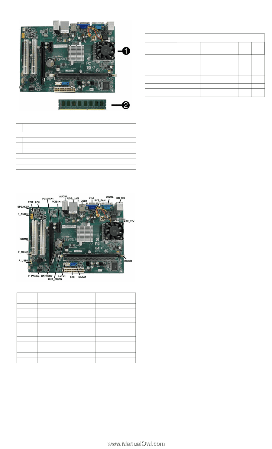
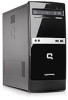
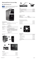
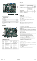
Power States The following table describes how button presses and generated events are handled in each power state. Buttons Pressed or Events Generated Handling in Each Power State Hibern Shut ate down On Standby (S1/S3) (S4) (S5) Power LED Status On With DLED in Type 11: Off Off Changes color from On (e.g. green vs. yellow). Other- wise: Blinks using the same color as in On (e.g. steady- blue vs. blinking-blue). Num/Caps/Scroll Lock -- Off LEDs (PS/2) Off Off LAN LED (power) On Off Off Off LAN LED (activity) Blinking - active Off Off - Otherwise Off Off Standard and Optional Boards 1 System board with VIA Nano U2250 processor (includes thermal material) Memory modules * 4 GB, PC3-10600 2 2 GB, PC3-10600 * 1 GB, PC3-10600 Other boards ATI Radeon HD4350 (RV710) PCIe x16 graphics card, 512 MB GeForce G205, PCIe graphics card, 512MB * Not shown System Board 630089-001 585157-001 576110-001 576109-001 637472-001 589146-001 System Board Connectors and Jumpers (position of some untitled components may vary in location) PCI2 PCI slot DIMM1 Memory slot PCI1 PCI slot SATA1 Hard drive connector PCIE16X1 PCIe x16 slot SATA2 Optical drive connector PCIE1X1 PCIe x1 slot ATX 24-pin main power connector (20-pins used) AUDIO External in/out connectors CLR_CMOS Clear CMOS jumper USB_LAN Stacked USB connectors/ Network connector BATTERY RTC battery socket R_USB1 Stacked USB connectors F_PANEL Front I/O connector VGA Monitor connector F_USB1 Front I/O connector SYS_FAN Fan connector F_USB2 Front I/O connector COMA Serial port connector COMB Serial port connector KB_MS Keyboard/mouse connectors F_AUDIO Front audio connector ATX_12V 4-pin CPU power connector SPEAKER Speaker connector Clearing CMOS The header allows you to clear the RTC RAM in CMOS. To erase the RTC RAM: 1. Turn off the computer and any external devices, and disconnect power. 2. Remove the access panel. 3. Remove the RTC battery. 4. Locate the CMOS jumper header on the motherboard. It is labeled CLR_CMOS. 5. Remove the jumper from pins 1-2 pins and put it on pins 2-3 to clear CMOS. Keep the cap on pins 2-3 for 5 to 10 seconds. 6. Replace the jumper on pins 1-2. 7. Reinstall the battery. 8. Replace the access panel, external devices, and reconnect the power cord. 9. Turn on the computer. 10.Hold down the F1 key during boot and enter BIOS setup to re-enter data. Hewlett-Packard Vision Diagnostics The Hewlett-Packard Vision Diagnostics utility allows you to view information about the hardware configuration of the computer and perform hardware diagnostic tests on the subsystems of the computer. The utility simplifies the process of effectively identifying, diagnosing, and isolating hardware issues. Use HP Vision Diagnostics to determine if all the devices installed on the computer are recognized by the system and functioning properly. Running tests is optional but recommended after installing or connecting a new device. To access HP Vision Diagnostics, you must create a Recovery Disc Set then boot to the CD containing the utility. It can also be downloaded from http://www.hp.com and either burned to CD or installed to a USB flash drive. 1. In Windows Explorer, go to C:\SWSetup\ISOs and burn the file Vision Diagnostics.ISO to a CD or copy it to a USB flash drive. 2. While the computer is on, insert the CD in the optical drive or USB flash drive in a USB port. 3. Shut down the operating system and turn off the computer. 4. Turn on the computer. The system will boot into HP Vision Diagnostics. NOTE: If the system does not boot to the CD in the optical drive or to the USB flash drive, you may need to change the boot order in the Computer Setup (F10) utility. 5. At the boot menu, select either the HP Vision Diagnostics utility to test the various hardware components in the computer or the HP Memory Test utility to test memory only. NOTE: The HP Memory Test is a comprehensive memory diagnostic utility that is run as a stand-alone application, outside of HP Vision Diagnostics. 6. If running HP Vision Diagnostics, select the appropriate language and click Continue. 7. In the End User License Agreement page, select Agree if you agree with the terms. The HP Vision Diagnostics utility launches with the Survey tab displayed. Using the Setup Utility The BIOS Setup Utility is accessed by pressing the F10 button during startup. The BIOS Setup Utility allows you to: • Change factory default settings • Set the system date and time • Set, view, change, or verify the system configuration, including settings for graphics, audio, storage, communications, and input devices • View processor and memory settings • Modify the boot order of bootable devices, such as hard drives, diskette drives, optical drives, or USB media • Run tests on the hard drive • Establish a supervisor password that controls access to the Setup Utility HP 303B, MT 630763-001 page 2
-
 1
1 -
 2
2 -
 3
3
 |
 |