HP 4x1x16 HP IP and Server Console Switches G2 User Guide - Page 20
Verifying connections
 |
View all HP 4x1x16 manuals
Add to My Manuals
Save this manual to your list of manuals |
Page 20 highlights
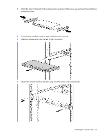
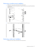
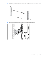
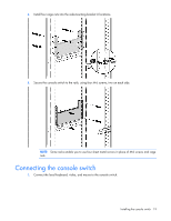
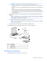
WARNING: To reduce the risk of electric shock or damage to the equipment: • Do not disable the power cord grounding plug. The grounding plug is an important safety feature. • Plug the power cord into a grounded (earthed) electrical outlet that is easily accessible at all times. • Unplug the power cord from the power supply to disconnect power to the equipment. • Do not route the power cord where it can be walked on or pinched by items placed against it. Pay particular attention to the plug, electrical outlet, and the point where the cord extends from the storage system. 2. Plug the console switch power cord into a power source. The power supply status indicator LED illuminates. NOTE: UTP CAT5 cables are used throughout the examples in this guide. However, UTP CAT5 or better cables can be used for any connection. 3. Connect a UTP CAT5 cable to the LAN connector on the console switch. NOTE: For console switches that have 2 LAN connectors, you must connect them to 2 Ethernet switches on the same subnet. 4. Connect the other end of that same UTP CAT5 cable to an Ethernet switch. The following figure shows one possible configuration for your console switch system. Item 1 2 3 Description Local console Console switch Ethernet switch Verifying connections The following LEDs illuminate to indicate connection status. Installing the console switch 20
-
 1
1 -
2
-
3
-
4
-
5
-
6
-
7
-
8
-
9
-
10
-
11
-
12
-
13
-
14
-
 15
15 -
 16
16 -
 17
17 -
 18
18 -
 19
19 -
 20
20 -
 21
21 -
 22
22 -
 23
23 -
 24
24 -
 25
25 -
26
-
27
-
28
-
29
-
30
-
31
-
32
-
33
-
34
-
35
-
36
-
37
-
38
-
39
-
40
-
41
-
42
-
43
-
44
-
45
-
46
-
47
-
48
-
49
-
50
-
51
-
52
-
53
-
54
-
55
-
56
-
57
-
58
-
59
-
60
-
61
-
62
-
63
-
64
-
65
-
66
-
67
-
68
-
69
-
70
-
71
-
72
-
73
-
74
-
75
-
76
-
77
-
78
-
79
-
80
-
81
-
82
-
83
 |
 |
