HP 515B Maintenance & Service Guide: HP 500B and 505B, Compaq 500B and 505 - Page 41
Front I/O and USB Panel Housing Assembly,
 |
View all HP 515B manuals
Add to My Manuals
Save this manual to your list of manuals |
Page 41 highlights
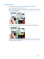
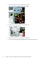
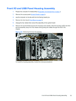
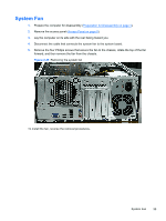
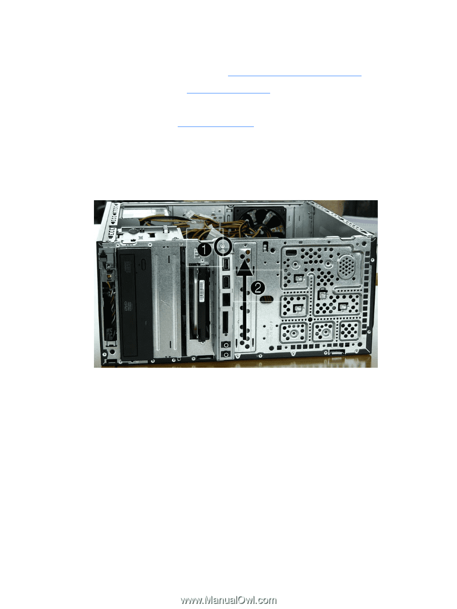
Front I/O and USB Panel Housing Assembly 1. Prepare the computer for disassembly (Preparation for Disassembly on page 4). 2. Remove the access panel (Access Panel on page 5) 3. Lay the computer on its side with the front facing toward you. 4. Remove the front bezel (Front Bezel on page 7). 5. Unplug the four cables that connect the assembly to the system board. 6. Remove the screw (1) that secures the housing to the chassis, slide the housing up (2), and then pull the assembly away from the chassis while guiding the cables through the hole in the chassis. Figure 2-43 Removing the front I/O assembly To install the housing assembly, reverse the removal procedures. Front I/O and USB Panel Housing Assembly 33
-
 1
1 -
2
-
3
-
4
-
5
-
6
-
7
-
8
-
9
-
10
-
11
-
12
-
13
-
14
-
15
-
16
-
17
-
18
-
19
-
20
-
21
-
22
-
23
-
24
-
25
-
26
-
27
-
28
-
29
-
30
-
31
-
32
-
33
-
34
-
35
-
 36
36 -
 37
37 -
 38
38 -
 39
39 -
 40
40 -
 41
41 -
 42
42 -
 43
43 -
 44
44 -
 45
45 -
 46
46 -
47
-
48
-
49
-
50
-
51
-
52
-
53
-
54
-
55
-
56
-
57
-
58
-
59
-
60
-
61
-
62
-
63
-
64
-
65
-
66
-
67
-
68
-
69
-
70
-
71
-
72
-
73
-
74
-
75
-
76
-
77
-
78
-
79
-
80
-
81
-
82
-
83
-
84
-
85
-
86
-
87
-
88
-
89
-
90
-
91
-
92
-
93
-
94
-
95
-
96
-
97
-
98
-
99
-
100
-
101
-
102
-
103
-
104
-
105
-
106
-
107
-
108
-
109
-
110
-
111
-
112
-
113
 |
 |
Front I/O and USB Panel Housing Assembly
1.
Prepare the computer for disassembly (
Preparation for Disassembly
on page
4
).
2.
Remove the access panel (
Access Panel
on page
5
)
3.
Lay the computer on its side with the front facing toward you.
4.
Remove the front bezel (
Front Bezel
on page
7
).
5.
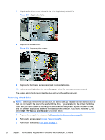
Unplug the four cables that connect the assembly to the system board.
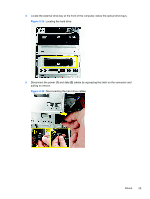
6.
Remove the screw
(1)
that secures the housing to the chassis, slide the housing up
(2)
, and then
pull the assembly away from the chassis while guiding the cables through the hole in the
chassis.
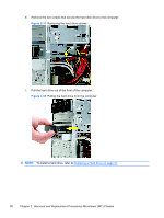
Figure 2-43
Removing the front I/O assembly
To install the housing assembly, reverse the removal procedures.
Front I/O and USB Panel Housing Assembly
33