HP 655 HP 655 Notebook PC - Maintenance and Service Guide - Page 52
that secure the optical drive bracket to the, Remove the two Phillips PM2.0×3.0 screws
 |
View all HP 655 manuals
Add to My Manuals
Save this manual to your list of manuals |
Page 52 highlights
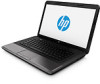
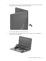
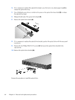
4. If it is necessary to replace the optical drive bezel, use a thin tool or an unbent paper clip (1) to release the optical drive tray. 5. Use a flat-blade screw driver or similar tool to press on the optical drive bezel tab (2) to release the optical drive bezel. 6. Release the left side of the optical drive bezel (3). 7. Remove the optical drive bezel (4). 8. If it is necessary to replace the optical drive bracket, position the optical drive with the rear panel toward you. 9. Remove the two Phillips PM2.0×3.0 screws (1) that secure the optical drive bracket to the optical drive. 10. Remove the optical drive bracket (2). Reverse this procedure to install the optical drive. 44 Chapter 4 Removal and replacement procedures
-
 1
1 -
2
-
3
-
4
-
5
-
6
-
7
-
8
-
9
-
10
-
11
-
12
-
13
-
14
-
15
-
16
-
17
-
18
-
19
-
20
-
21
-
22
-
23
-
24
-
25
-
26
-
27
-
28
-
29
-
30
-
31
-
32
-
33
-
34
-
35
-
36
-
37
-
38
-
39
-
40
-
41
-
42
-
43
-
44
-
45
-
46
-
 47
47 -
 48
48 -
 49
49 -
 50
50 -
 51
51 -
 52
52 -
 53
53 -
 54
54 -
 55
55 -
 56
56 -
 57
57 -
58
-
59
-
60
-
61
-
62
-
63
-
64
-
65
-
66
-
67
-
68
-
69
-
70
-
71
-
72
-
73
-
74
-
75
-
76
-
77
-
78
-
79
-
80
-
81
-
82
-
83
-
84
-
85
-
86
-
87
-
88
-
89
-
90
-
91
-
92
-
93
-
94
-
95
-
96
-
97
-
98
-
99
-
100
-
101
-
102
-
103
-
104
-
105
 |
 |

4.
If it is necessary to replace the optical drive bezel, use a thin tool or an unbent paper clip
(1)
to
release the optical drive tray.
5.
Use a flat-blade screw driver or similar tool to press on the optical drive bezel tab
(2)
to release
the optical drive bezel.
6.
Release the left side of the optical drive bezel
(3)
.
7.
Remove the optical drive bezel
(4)
.
8.
If it is necessary to replace the optical drive bracket, position the optical drive with the rear panel
toward you.
9.
Remove the two Phillips PM2.0×3.0 screws
(1)
that secure the optical drive bracket to the
optical drive.
10.
Remove the optical drive bracket
(2)
.
Reverse this procedure to install the optical drive.
44
Chapter 4
Removal and replacement procedures