HP 6820s HP Compaq 6820s Notebook PC - Maintenance and Service Guide - Page 61
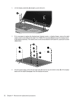
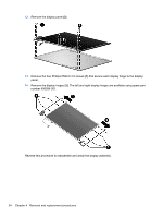
Display assembly, Remove the four Torx T8M2.5×7.0 screws
 |
UPC - 883585963447
View all HP 6820s manuals
Add to My Manuals
Save this manual to your list of manuals |
Page 61 highlights
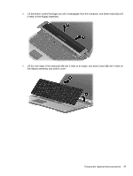
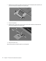
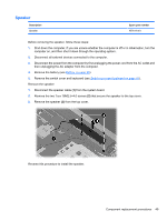
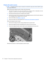
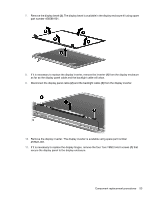
Display assembly NOTE: All display assembly spare part kits include 2 WLAN antenna transceivers and cables. Description 17.0-inch, WXGA with AntiGlare 17.0-inch, WXGA with BrightView Spare part number 456582-001 456583-001 Before removing the display assembly, follow these steps: 1. Shut down the computer. If you are unsure whether the computer is off or in Hibernation, turn the computer on, and then shut it down through the operating system. 2. Disconnect all external devices connected to the computer. 3. Disconnect the power from the computer by first unplugging the power cord from the AC outlet and then unplugging the AC adapter from the computer. 4. Remove the battery (see Battery on page 35). 5. Disconnect the wireless antenna cables from the WLAN module (see WLAN module on page 38). 6. Remove the following components: a. Switch cover and keyboard (see Switch cover and keyboard on page 45) b. Speaker (see Speaker on page 49) c. Display lid switch module (see Display lid switch module on page 50) Remove the display assembly: 1. Disconnect the display panel cables (1) and (2) from the system board. 2. Remove the wireless antenna cables (3) from the clips and routing channels built into the top cover. 3. Remove the four Torx T8M2.5×7.0 screws (1) that secure the display assembly to the computer. Component replacement procedures 51
-
 1
1 -
2
-
3
-
4
-
5
-
6
-
7
-
8
-
9
-
10
-
11
-
12
-
13
-
14
-
15
-
16
-
17
-
18
-
19
-
20
-
21
-
22
-
23
-
24
-
25
-
26
-
27
-
28
-
29
-
30
-
31
-
32
-
33
-
34
-
35
-
36
-
37
-
38
-
39
-
40
-
41
-
42
-
43
-
44
-
45
-
46
-
47
-
48
-
49
-
50
-
51
-
52
-
53
-
54
-
55
-
 56
56 -
 57
57 -
 58
58 -
 59
59 -
 60
60 -
 61
61 -
 62
62 -
 63
63 -
 64
64 -
 65
65 -
 66
66 -
67
-
68
-
69
-
70
-
71
-
72
-
73
-
74
-
75
-
76
-
77
-
78
-
79
-
80
-
81
-
82
-
83
-
84
-
85
-
86
-
87
-
88
-
89
-
90
-
91
-
92
-
93
-
94
-
95
-
96
-
97
-
98
-
99
-
100
-
101
-
102
-
103
-
104
-
105
-
106
-
107
-
108
-
109
-
110
-
111
-
112
-
113
-
114
-
115
-
116
-
117
-
118
-
119
-
120
-
121
-
122
-
123
-
124
-
125
-
126
-
127
-
128
-
129
-
130
-
131
-
132
-
133
-
134
-
135
-
136
-
137
-
138
-
139
-
140
-
141
-
142
-
143
-
144
-
145
-
146
-
147
-
148
-
149
 |
 |