HP BL2x220c Processor Option Installation Instructions for the HP ProLiant BL2 - Page 2
Caution, Important
 |
View all HP BL2x220c manuals
Add to My Manuals
Save this manual to your list of manuals |
Page 2 highlights
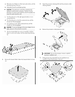
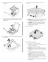
a. Place the server blade on a flat, level work surface with the bezel facing away from you. b. Extend the server B serial label pull tab. CAUTION: The jackscrews control the unseating and seating of critical system connectors. Failure to use the jackscrews to remove and install the server B assembly can cause the system boards to fail. c. Turn the jackscrew on the right approximately six turns counterclockwise. d. Turn the jackscrew on the left counterclockwise until the threads are fully disengaged. e. Turn jackscrew on the right counterclockwise until the threads are fully disengaged. CAUTION: To prevent damage to the server blade, do not apply pressure to the enclosure connector. f. Lift server B assembly from server A assembly, and then place it on the work surface with the system board facing up. 5. Open the processor retaining latch and the processor socket retaining bracket. 6. Remove the processor socket protective cover. 4. Remove the heatsink blank. Retain the heatsink blank for future use. IMPORTANT: Be sure the processor remains inside the processor installation tool. 7. If the processor has separated from the installation tool, carefully re-insert the processor in the tool.
-
 1
1 -
 2
2 -
 3
3 -
 4
4
 |
 |
