HP Beats Special Edition 15-p300 Pavilion 17 Notebook PC Pavilion 15 Notebook - Page 71
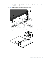
transceivers are attached to the display bezel with double-sided tape.
 |
View all HP Beats Special Edition 15-p300 manuals
Add to My Manuals
Save this manual to your list of manuals |
Page 71 highlights
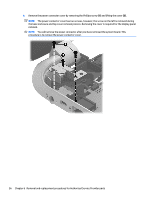
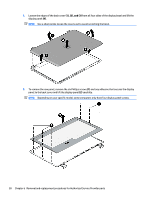
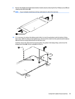
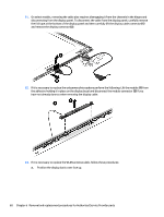
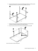
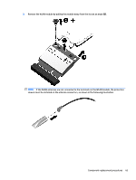
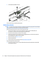
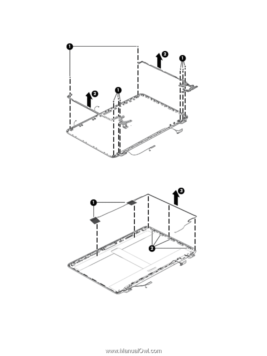
b. Remove the display brackets by removing the eight Phillips and broadhead screws (1) securing the hinge brackets to the back cover, and then lift the brackets (2) to remove them. c. Release the wireless antenna transceivers (1) from the display bezel. (The wireless antenna transceivers are attached to the display bezel with double-sided tape.) d. Remove the wireless antenna from the retaining channels (2), and lift the antenna (3) Reverse this procedure to install the display panel. Component replacement procedures 61
-
 1
1 -
2
-
3
-
4
-
5
-
6
-
7
-
8
-
9
-
10
-
11
-
12
-
13
-
14
-
15
-
16
-
17
-
18
-
19
-
20
-
21
-
22
-
23
-
24
-
25
-
26
-
27
-
28
-
29
-
30
-
31
-
32
-
33
-
34
-
35
-
36
-
37
-
38
-
39
-
40
-
41
-
42
-
43
-
44
-
45
-
46
-
47
-
48
-
49
-
50
-
51
-
52
-
53
-
54
-
55
-
56
-
57
-
58
-
59
-
60
-
61
-
62
-
63
-
64
-
65
-
 66
66 -
 67
67 -
 68
68 -
 69
69 -
 70
70 -
 71
71 -
 72
72 -
 73
73 -
 74
74 -
 75
75 -
 76
76 -
77
-
78
-
79
-
80
-
81
-
82
-
83
-
84
-
85
-
86
-
87
-
88
-
89
-
90
-
91
-
92
-
93
-
94
-
95
-
96
-
97
-
98
-
99
-
100
-
101
-
102
-
103
-
104
-
105
-
106
-
107
-
108
-
109
-
110
-
111
-
112
-
113
-
114
-
115
-
116
-
117
-
118
-
119
-
120
-
121
-
122
-
123
-
124
-
125
-
126
-
127
-
128
 |
 |
b.
Remove the display brackets by removing the eight Phillips and broadhead screws
(1)
securing the
hinge brackets to the back cover, and then lift the brackets
(2)
to remove them.
c.
Release the wireless antenna transceivers
(1)
from the display bezel. (The wireless antenna
transceivers are attached to the display bezel with double-sided tape.)
d.
Remove the wireless antenna from the retaining channels
(2)
, and lift the antenna
(3)
Reverse this procedure to install the display panel.
Component replacement procedures
61