HP C7770B HP DesignJet 500Plus Printers - D/A1-size Stand and Paper Bin Setup
HP C7770B - DesignJet 500 Color Inkjet Printer Manual
 |
UPC - 725184439704
View all HP C7770B manuals
Add to My Manuals
Save this manual to your list of manuals |
HP C7770B manual content summary:
- HP C7770B | HP DesignJet 500Plus Printers - D/A1-size Stand and Paper Bin Setup - Page 1
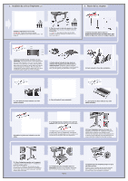
HP DesignJet 500 and 800 Series Printers D/A1-size Stand and Paper Bin- Assembly Instructions Copyright Hewlett-Packard Company 2000 Part Number C7769-90161 First Edition September 2000 Printed in Europe Hewlett-Packard Company Inkjet Commercial Division Avda. Graells, 501 08190 Sant Cugat del - HP C7770B | HP DesignJet 500Plus Printers - D/A1-size Stand and Paper Bin Setup - Page 2
2. Attach the Stand to the Printer (continued) 3. Assemble the Paper Bin 4-Put the printer onto the stand assembly. WARNING: 2 people should support the printer while a third secures the stand-see step 5. 5-Secure the stand with the four screws that have large flat heads. Two screws (on one leg) - HP C7770B | HP DesignJet 500Plus Printers - D/A1-size Stand and Paper Bin Setup - Page 3
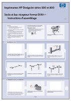
Imprimantes HP DesignJet séries 500 et 800 Socle et bac récepteur format D/A1- Instructions d'assemblage Français Sommaire 1. Assemblage du socle (page 1) 2. Installation du socle sur l'imprimante (page 1) 3. Fixation du bac récepteur (page 2) Les informations contenues sur ce poster - HP C7770B | HP DesignJet 500Plus Printers - D/A1-size Stand and Paper Bin Setup - Page 4
ée du cercle d'orientation. 3-Faites glisser la bande du bac dans les rainures des supports, puis pliez-la pour la mettre en place. Introduisez d'abord l'extrémité compos montants, puis introduire le bac récepteur dans ces adaptateurs. 10-Fixez l'adaptateur droit sur le socle. Cet adaptateur porte - HP C7770B | HP DesignJet 500Plus Printers - D/A1-size Stand and Paper Bin Setup - Page 5
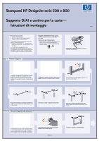
Stampanti HP DesignJet serie 500 e 800 Supporto D/A1 e cestino per la carta- Istruzioni di montaggio Italiano Contenuto di questo sono valide per i seguenti prodotti HP: • Supporto e cestino per la carta supplementari per i modelli di dimensioni D/A1 - numeri di parte C7781A e C7782A. Se si - HP C7770B | HP DesignJet 500Plus Printers - D/A1-size Stand and Paper Bin Setup - Page 6
stampante; quindi il cestino verrà inserito negli alloggiamenti. 10-Montare l'adattatore di destra sul supporto. È contrassegnato dalla lettera 'R' e deve essere montato sulla parte frontale della gamba destra. Agganciare la parte inferiore all'alloggiamento, quindi drizzare il supporto; quando la - HP C7770B | HP DesignJet 500Plus Printers - D/A1-size Stand and Paper Bin Setup - Page 7
HP DesignJet 500 und 800 Series Drucker Aufbauanleitung für die Aufstellvorrichtung und Papierablage für D/A1-Format-Modelle (Seite 2) Die Informationen in diesem Poster beziehen sich auf die folgenden HP Produkte: • Aufstellvorrichtung und Papierablage für D/A1- Format-Modelle - Teilenummer - HP C7770B | HP DesignJet 500Plus Printers - D/A1-size Stand and Paper Bin Setup - Page 8
der Aufstellvorrichtung des Druckers mit zwei Adaptern montiert, die zuerst in den Standbeinen einzusetzen sind. Dann wird die Ablage in den Adaptern eingesetzt. 10-Bringen Sie den rechten Adapter an der Aufstellvorrichtung an. Er ist mit dem Buchstaben 'R' markiert und muß auf der Vorderseite des - HP C7770B | HP DesignJet 500Plus Printers - D/A1-size Stand and Paper Bin Setup - Page 9
Impresoras HP DesignJet Serie 500 y 800 Base y bandeja de papel de tamaño D/A1 - Instrucciones de montaje del soporte. Así tendrá acceso a los componentes del soporte. 2-Conecte las patas a la parte exterior de la abrazadera cruzada. Observe que el soporte está montado de arriba a abajo. 3-Inserte - HP C7770B | HP DesignJet 500Plus Printers - D/A1-size Stand and Paper Bin Setup - Page 10
en las patas; a continuación la bandeja se ajusta a los adaptadores. 10-Conecte el adaptador derecho al soporte. Está marcado con la letra 'R' y debe conectarse a la parte frontal de la pata derecha. Encaje primero la parte inferior en la ranura y a continuación levántela; debe escuchar dos clics - HP C7770B | HP DesignJet 500Plus Printers - D/A1-size Stand and Paper Bin Setup - Page 11
Impressoras HP DesignJet Série 500 e 800 Suporte e bandeja de papel D/A1- Instruções de montagem Português Conteúdo deste pôster da impressora. Isso lhe dá acesso aos componentes do suporte. 2-Prenda os pedestais à parte externa do suporte central. Note que o suporte está montado de cabeça para - HP C7770B | HP DesignJet 500Plus Printers - D/A1-size Stand and Paper Bin Setup - Page 12
ser localizados nas pernas da impressora; então a bandeja será encaixada nos adaptadores. 10-Conecte o adaptador direito ao suporte. Está marcado com a letra 'R' e deve ser conectada na frente da perna direita. Prenda a parte inferior em seu slot e, em seguida, levante-a para seu lugar; você deve
-
 1
1 -
 2
2 -
 3
3 -
 4
4 -
 5
5 -
 6
6 -
 7
7 -
8
-
9
-
10
-
11
-
12
 |
 |
Page 1
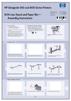
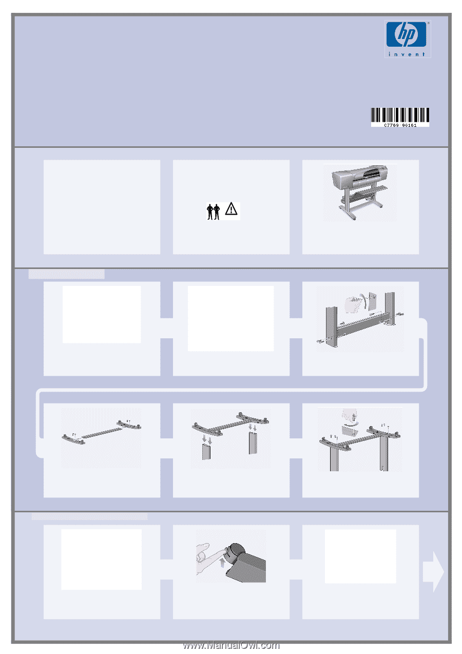
HP DesignJet 500 and 800 Series Printers
D/A1-size Stand and Paper Bin—
Assembly Instructions
Contents of This Poster
1.
Assemble the Stand (page 1)
2.
Attach the Stand to the Printer (page 2)
3.
Assemble the Paper Bin (page 2)
The information on this poster applies to the following
HP products:
•
Stand and Paper Bin accessory for the D/A1-size
models–part numbers C7781A and C7782A.
If you are installing this
accessory
after the main
installation has been completed, use these instructions.
If you are installing it at the same time as the main
installation, read the appropriate stages of the
Assembly
and Set-Up Instructions Poster
for the printer.
Read these instructions carefully...
and complete each stage before you start the next.
What You Will Need to Do the Job
•
Because some of the components of the printer are
bulky, you will need
2 or 3 people
to lift them.
See
the descriptions that follow for details—a symbol like
this is used:
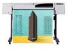
The D/A1-size printer
with its stand and paper bin
attached.
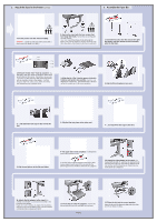
1–Separate the stand from the paper bin.
Set
aside the cardboard tray inside which separates the
components of the paper bin from those of the printer’s
stand.
This gives you access to the stand components.
2–Attach the legs to the outside of the cross
brace.
Note that the stand is assembled upside-down.
3–Insert eight screws into the legs.
Use the
smaller screws with washers.
4–Position the horizontal foot brace onto the
feet.
Push the foot brace into the slot in each foot.
5–Position the feet on the legs assembly.
6–Secure the feet to the legs with ten screws.
Again, use the smaller screws with washers.
1–Check that all the stand screws are tight.
If you can’t tighten all the screws properly, try
unscrewing one or two so that the legs, feet and cross
braces are properly aligned, and then retighten them.
2–Ensure all four brakes are applied, as shown.
3–Turn the stand the correct way up.
1.
Assemble the Stand
2.
Attach the Stand to the Printer
Copyright Hewlett-Packard
Company 2000
Part Number C7769-90161
First Edition
September 2000
Printed in Europe
Hewlett-Packard Company
Inkjet Commercial Division
Avda. Graells, 501
08190 Sant Cugat del Vallès
Barcelona, Spain