HP Cc3310 User Information and Service Guide - HP Carrier-Grade Server cc3310 - Page 103
Memory
 |
View all HP Cc3310 manuals
Add to My Manuals
Save this manual to your list of manuals |
Page 103 highlights
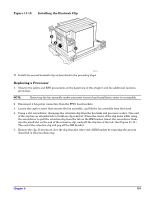
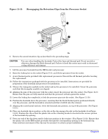
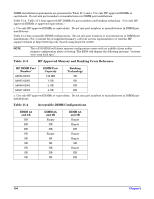
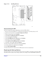
18. Press the other end of the clip down into position on the retainer (C in Figure 11-12). Ensure that the plastic tab on the RM bracket protrudes through the corresponding opening in the heatsink clip. 19. Install the second heatsink clip as described in the preceding steps. Reprogramming the SDR If you have changed the processor configuration, rewrite the SDR as follows: 1. Boot the system from the HP Server cc3310 Information Diagnostics and Utilities Resource CD. 2. After the server has booted, select Load Configuration Wizard. 3. When the wizard begins, press Continue. 4. Select Server Configuration Wizard and Continue. 5. Select run wizard and Continue. 6. Select Load SDRs only on to this server and Continue. 7. Set the date and time and select Continue. 8. Select Update just the SDR repository and Continue. 9. Select Yes - Activate BMC TAM and Continue. 10. Choose the desired LED configuration and select Continue. 11. Save the configuration to disk and select Continue. 12. Select OK to program SDRs. 13. Observe that the server reboots when the SDR repository has been reprogrammed. Memory CAUTION The system Sensor Data Records (SDR) must be reprogrammed every time that the memory configuration is changed. Failure to reprogram the SRD may allow critical system failures to occur without an appropriate Telco alarm. Failure to recognize an alarm condition could result in loss of data or damage to equipment. NOTE Only DDR266 is supported with a 533 MHz front side bus. DIMMs must be installed in pairs and in the following order: 1A and 1B, 2A and 2B, 3A and 3B. The server board supports only DDR266 compliant SDRAM. Install from 256 MB to 12 GB of approved ECC memory, using up to six DIMMs. If DIMM sizes are to be mixed, install DIMMs in order by capacity. Install the smaller capacity DIMMs in slots 1A and 1B, the same or larger DIMMs in slots 2A and 2B, and the largest DIMMs in slots 3A and 3B. Example: 1. Install the 512 MB DIMM pair in SLOTs 1A/B (2 each 256M DIMMs). 2. Install the 1 GB DIMM pair in SLOTs 2A/B (2 each 512M DIMMs). 3. Install the 2 GB DIMM pair in SLOTs 3A/B (2 each 1 GB DIMMs). DIMM pairs must be identical. (Do not mix sizes or manufacturers.) Installed DIMMs must be the same speed. Chapter 9 103
-
 1
1 -
2
-
3
-
4
-
5
-
6
-
7
-
8
-
9
-
10
-
11
-
12
-
13
-
14
-
15
-
16
-
17
-
18
-
19
-
20
-
21
-
22
-
23
-
24
-
25
-
26
-
27
-
28
-
29
-
30
-
31
-
32
-
33
-
34
-
35
-
36
-
37
-
38
-
39
-
40
-
41
-
42
-
43
-
44
-
45
-
46
-
47
-
48
-
49
-
50
-
51
-
52
-
53
-
54
-
55
-
56
-
57
-
58
-
59
-
60
-
61
-
62
-
63
-
64
-
65
-
66
-
67
-
68
-
69
-
70
-
71
-
72
-
73
-
74
-
75
-
76
-
77
-
78
-
79
-
80
-
81
-
82
-
83
-
84
-
85
-
86
-
87
-
88
-
89
-
90
-
91
-
92
-
93
-
94
-
95
-
96
-
97
-
 98
98 -
 99
99 -
 100
100 -
 101
101 -
 102
102 -
 103
103 -
 104
104 -
 105
105 -
 106
106 -
 107
107 -
 108
108 -
109
-
110
-
111
-
112
-
113
-
114
-
115
-
116
-
117
-
118
-
119
-
120
-
121
-
122
-
123
-
124
-
125
 |
 |
