HP Cc3310 UserÆs Guide and Technical UserÆs Guide - HP Carri - Page 6

HP Cc3310 - Server - AC Option Manual

Page 6 highlights

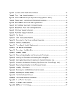
Figures Figure 1. cc2300 Carrier Grade Server Chassis 13 Figure 2. Front Panel Control Locations 16 Figure 3. DC Input Back Panel (AC Input Power Supply Shown Below 18 Figure 4. Server Board Connector and Component Locations 19 Figure 5. 3.3 Volt Riser Board with Half-height Bracket 29 Figure 6. 3.3 Volt Riser Board with Full-height Bracket 29 Figure 7. 5 Volt Riser Board with Full-height Bracket 30 Figure 8. DC-Power Supply Subsystem 31 Figure 9. AC-Power Supply Subsystem 34 Figure 10. Fan Module...36 Figure 11. Tools and Supplies Needed 63 Figure 12. Removing the Top Cover and Bezel Assembly 66 Figure 13. Internal Chassis Layout 67 Figure 14. Power Supply Module Replacement 68 Figure 15. Fan Module Replacement 69 Figure 16. Removing a Hard Disk Drive 70 Figure 17. Installing DIMMs ...73 Figure 18. Raising the Locking Bar and Removing the Terminator 75 Figure 19. Inserting the Processor and Lowering the Locking Bar 76 Figure 20. Aligning the Heatsink and Installing the Heatsink Retaining Clip 77 Figure 21. Unlatching the Heatsink Retaining Clip (Shown from Power Supply Side 78 Figure 22. Raising the Locking Bar on the Processor Socket 78 Figure 23. Installing a Terminator 79 Figure 24. Removing the CD-ROM Drive from the Carrier 86 Figure 25. Replacing the Backup Battery 87 Figure 28. Front Panel Board Removal 90 Figure 29. Front Panel Serial Port Connector 93 Figure 30. 15-pin Alarms Connector 94 Figure 31. DC Power Input Connector 95 Figure 32. DC Power Terminal Lug 95 vi cc2300 Carrier Grade Server Product Guide

  • 1
  • 2
  • 3
  • 4
  • 5
  • 6
  • 7
  • 8
  • 9
  • 10
  • 11
  • 12
  • 13
  • 14
  • 15
  • 16
  • 17
  • 18
  • 19
  • 20
  • 21
  • 22
  • 23
  • 24
  • 25
  • 26
  • 27
  • 28
  • 29
  • 30
  • 31
  • 32
  • 33
  • 34
  • 35
  • 36
  • 37
  • 38
  • 39
  • 40
  • 41
  • 42
  • 43
  • 44
  • 45
  • 46
  • 47
  • 48
  • 49
  • 50
  • 51
  • 52
  • 53
  • 54
  • 55
  • 56
  • 57
  • 58
  • 59
  • 60
  • 61
  • 62
  • 63
  • 64
  • 65
  • 66
  • 67
  • 68
  • 69
  • 70
  • 71
  • 72
  • 73
  • 74
  • 75
  • 76
  • 77
  • 78
  • 79
  • 80
  • 81
  • 82
  • 83
  • 84
  • 85
  • 86
  • 87
  • 88
  • 89
  • 90
  • 91
  • 92
  • 93
  • 94
  • 95
  • 96
  • 97
  • 98
  • 99
  • 100
  • 101
  • 102
  • 103
  • 104
  • 105
  • 106
  • 107
  • 108
  • 109
  • 110
  • 111
  • 112
  • 113
  • 114
  • 115
  • 116
  • 117
  • 118
  • 119
  • 120
  • 121
  • 122
  • 123
  • 124
  • 125
  • 126
  • 127
  • 128
  • 129
  • 130
  • 131
  • 132
  • 133
  • 134
  • 135

vi
cc2300 Carrier Grade Server Product Guide
Figures
Figure 1.
cc2300 Carrier Grade Server Chassis
........................................................................
13
Figure 2.
Front Panel Control Locations
....................................................................................
16
Figure 3.
DC Input Back Panel (AC Input Power Supply Shown Below)
...................................
18
Figure 4.
Server Board Connector and Component Locations
..................................................
19
Figure 5.
3.3 Volt Riser Board with Half-height Bracket
.............................................................
29
Figure 6.
3.3 Volt Riser Board with Full-height Bracket
.............................................................
29
Figure 7.
5 Volt Riser Board with Full-height Bracket
................................................................
30
Figure 8.
DC-Power Supply Subsystem
....................................................................................
31
Figure 9.
AC-Power Supply Subsystem
.....................................................................................
34
Figure 10.
Fan Module
...............................................................................................................
36
Figure 11.
Tools and Supplies Needed
......................................................................................
63
Figure 12.
Removing the Top Cover and Bezel Assembly
........................................................
66
Figure 13.
Internal Chassis Layout
............................................................................................
67
Figure 14.
Power Supply Module Replacement
.........................................................................
68
Figure 15.
Fan Module Replacement
.........................................................................................
69
Figure 16.
Removing a Hard Disk Drive
....................................................................................
70
Figure 17.
Installing DIMMs
.......................................................................................................
73
Figure 18.
Raising the Locking Bar and Removing the Terminator
...........................................
75
Figure 19.
Inserting the Processor and Lowering the Locking Bar
............................................
76
Figure 20.
Aligning the Heatsink and Installing the Heatsink Retaining Clip
.............................
77
Figure 21.
Unlatching the Heatsink Retaining Clip (Shown from Power Supply Side)
...............
78
Figure 22.
Raising the Locking Bar on the Processor Socket
....................................................
78
Figure 23.
Installing a Terminator
..............................................................................................
79
Figure 24.
Removing the CD-ROM Drive from the Carrier
........................................................
86
Figure 25.
Replacing the Backup Battery
..................................................................................
87
Figure 28.
Front Panel Board Removal
.....................................................................................
90
Figure 29.
Front Panel Serial Port Connector
............................................................................
93
Figure 30.
15-pin Alarms Connector
..........................................................................................
94
Figure 31.
DC Power Input Connector
.......................................................................................
95
Figure 32.
DC Power Terminal Lug
...........................................................................................
95