HP Cisco MDS 9020 Cisco MDS 9100 Series Hardware Installation Guide (OL-17951- - Page 34
Front-Facing Installation, Description, Quantity
 |
View all HP Cisco MDS 9020 manuals
Add to My Manuals
Save this manual to your list of manuals |
Page 34 highlights
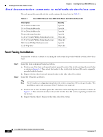
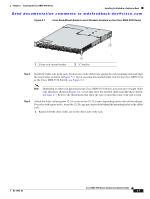
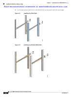
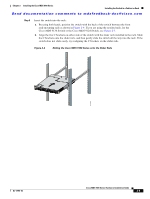
Installing the Switch in a Cabinet or Rack Chapter 2 Installing the Cisco MDS 9100 Series Send documentation comments to [email protected] The rack-mount kit provided with the switch contains the items listed in Table 2-1. Table 2-1 Cisco MDS 9134 and Cisco MDS 9124 Fabric Switch Rack-Mount Kit Description 30- to 36-inch slider rails 24- to 30-inch slider rails 18- to 24-inch slider rails Front rack-mount brackets 12-24 x 3/4-inch Phillips binder-head screws 10-32 x 3/4-inch Phillips binder-head screws M4 x 6-mm Phillips flat-head screws 12-24 Cage nuts Quantity 2 per kit 2 per kit 2 per kit 2 per kit 10 per kit 10 per kit 6 per kit 10 per kit Front-Facing Installation To install the switch in a cabinet or rack using the rack-mount kit provided with the switch, follow these steps: Step 1 Step 2 Install the front rack-mount bracket as follows: a. Position one of the front rack-mount brackets against the side of the switch and align the screw holes as shown in Figure 2-1. Then attach the bracket to the switch with the three M4 screws originally provided with the bracket. b. Repeat with the other front rack-mount bracket on the other side of the switch. Install the C brackets as follows: Note Two C brackets are shipped preinstalled on the switch, using three M3 screws per bracket. This installation step is only necessary if the C brackets were removed. a. Position one of the C brackets against the side of the switch and align the screw holes as shown in Figure 2-1. Then attach the bracket to the switch with the three M3 screws originally provided with the bracket. b. Repeat with the other C bracket on the other side of the switch. Cisco MDS 9100 Series Hardware Installation Guide 2-6 OL-17951-02
-
 1
1 -
2
-
3
-
4
-
5
-
6
-
7
-
8
-
9
-
10
-
11
-
12
-
13
-
14
-
15
-
16
-
17
-
18
-
19
-
20
-
21
-
22
-
23
-
24
-
25
-
26
-
27
-
28
-
 29
29 -
 30
30 -
 31
31 -
 32
32 -
 33
33 -
 34
34 -
 35
35 -
 36
36 -
 37
37 -
 38
38 -
 39
39 -
40
-
41
-
42
-
43
-
44
-
45
-
46
-
47
-
48
-
49
-
50
-
51
-
52
-
53
-
54
-
55
-
56
-
57
-
58
-
59
-
60
-
61
-
62
-
63
-
64
-
65
-
66
-
67
-
68
-
69
-
70
-
71
-
72
-
73
-
74
-
75
-
76
-
77
-
78
-
79
-
80
-
81
-
82
-
83
-
84
-
85
-
86
-
87
-
88
-
89
-
90
-
91
-
92
-
93
-
94
-
95
-
96
-
97
-
98
-
99
-
100
-
101
-
102
-
103
-
104
-
105
-
106
-
107
-
108
 |
 |
