HP Cisco MDS 9120 Cisco MDS 9100 Series Hardware Installation Guide (OL-17951- - Page 53
Cisco MDS 9000 Family Troubleshooting Guide, Cisco MDS 9000 Family, System Messages Guide
 |
View all HP Cisco MDS 9120 manuals
Add to My Manuals
Save this manual to your list of manuals |
Page 53 highlights
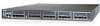
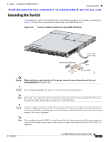
Chapter 2 Installing the Cisco MDS 9100 Series Starting Up the Switch Send documentation comments to [email protected] Step 4 Step 5 Step 6 Ensure that the switch is adequately grounded as described in the "Installing the Switch in a Cabinet with Insufficient Front Clearance" section on page 2-11, and that the power cables are connected to outlets that have the required AC power voltages (provided in the "Power Specifications" section on page B-2). Flip the power switches on the power supplies to the on (|) position. The switch boots automatically. Listen for the fans; they should begin operating as soon as the switch is powered on. Caution Do not operate the switch without a functioning fan module except for during the brief fan module replacement procedure. The Cisco MDS 9000 Family switches can operate for only a few minutes without any functioning fan modules before they begin to overheat. Step 7 Verify that the LED behavior is as follows when the switch has finished booting: • Fan status LED is green. • Each power supply LED is green. • The Switch status LED is green. If this LED is orange or red, then one or more environmental monitors is reporting a problem. • The Ethernet port Link LEDs should not be on unless the cable is connected. Note The LEDs for the Fibre Channel ports remain orange until the ports are enabled, and the LED for the MGMT 10/100 Ethernet port remains off until the port is connected. Step 8 If any LEDs other than the Fibre Channel port LEDs are orange or red after the initial boot processes are complete, see the Cisco MDS 9000 Family Troubleshooting Guide. Try removing and reinstalling a component that is not operating properly. If it still does not operate correctly, contact your customer service representative for a replacement. Note If you purchased Cisco support through a Cisco reseller, contact the reseller directly. If you purchased support directly from Cisco, contact Cisco Technical Support at this URL: http://www.cisco.com/warp/public/687/Directory/DirTAC.shtm Step 9 Step 10 Verify that the system software has booted and the switch has initialized without error messages. If any problems occur, see the Cisco MDS 9000 Family Troubleshooting Guide or the Cisco MDS 9000 Family System Messages Guide. If you cannot resolve an issue, contact your customer service representative. Complete the worksheets provided in Appendix D, "Site Planning and Maintenance Records" for future reference. Note A setup utility automatically launches the first time you access the switch and guides you through the basic configuration. For instructions about how to configure the switch and check module connectivity, see the Cisco MDS 9000 Family CLI Configuration Guide. OL-17951-02 Cisco MDS 9100 Series Hardware Installation Guide 2-25
-
 1
1 -
2
-
3
-
4
-
5
-
6
-
7
-
8
-
9
-
10
-
11
-
12
-
13
-
14
-
15
-
16
-
17
-
18
-
19
-
20
-
21
-
22
-
23
-
24
-
25
-
26
-
27
-
28
-
29
-
30
-
31
-
32
-
33
-
34
-
35
-
36
-
37
-
38
-
39
-
40
-
41
-
42
-
43
-
44
-
45
-
46
-
47
-
 48
48 -
 49
49 -
 50
50 -
 51
51 -
 52
52 -
 53
53 -
 54
54 -
 55
55 -
 56
56 -
 57
57 -
 58
58 -
59
-
60
-
61
-
62
-
63
-
64
-
65
-
66
-
67
-
68
-
69
-
70
-
71
-
72
-
73
-
74
-
75
-
76
-
77
-
78
-
79
-
80
-
81
-
82
-
83
-
84
-
85
-
86
-
87
-
88
-
89
-
90
-
91
-
92
-
93
-
94
-
95
-
96
-
97
-
98
-
99
-
100
-
101
-
102
-
103
-
104
-
105
-
106
-
107
-
108
 |
 |