HP Cluster Platform Hardware Kits v2010 HP Cluster Platform ProLiant G6 and G7 - Page 67
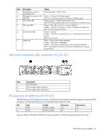
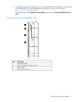
Interconnect module bay numbering
 |
View all HP Cluster Platform Hardware Kits v2010 manuals
Add to My Manuals
Save this manual to your list of manuals |
Page 67 highlights
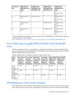
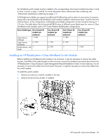
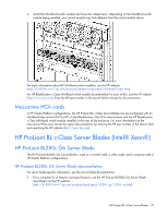
Interconnect module bay numbering Always install interconnect modules in the appropriate interconnect bays to support network connections for specific signals. Server blade signal NICs 1, 2, 3, and 4 (embedded) Mezzanine 1 Mezzanine 2 Mezzanine 3 Interconnect bay number 1, 2 3, 4 5, 6 and then 7, 8 7, 8 and then 5, 6 Interconnect bay label For interconnect-specific information, see the documentation that ships with the interconnect module. Port mapping: HP BladeSystem c7000 Enclosure interconnect module bay to server blade The following table maps the server blade embedded NICs and mezzanine port slot assignments for the different server blade types to the enclosure interconnect module bays. Interconnect bay 1 Single-density half-height server blade NIC 1 (embedded) Double-density half-height server blade (Server A) NIC 1 (embedded) 2 NIC 2 (embedded) - 3 Mezzanine slot 1, NIC 2 (embedded) port 1 4 Mezzanine slot 1, - port 1 5 Mezzanine slot 2, Mezzanine port 1 Double-density half-height server blade (Server B) - NIC 1 (embedded) - NIC 2 (embedded) - Single-density full-height server blade NIC 3 (embedded) NIC 1 (embedded) NIC 4 (embedded) NIC 2 (embedded) Mezzanine slot 1, port 1 Mezzanine slot 1, port 1 Mezzanine slot 2, HP ProLiant BL c-Class Server Blades 67
-
 1
1 -
2
-
3
-
4
-
5
-
6
-
7
-
8
-
9
-
10
-
11
-
12
-
13
-
14
-
15
-
16
-
17
-
18
-
19
-
20
-
21
-
22
-
23
-
24
-
25
-
26
-
27
-
28
-
29
-
30
-
31
-
32
-
33
-
34
-
35
-
36
-
37
-
38
-
39
-
40
-
41
-
42
-
43
-
44
-
45
-
46
-
47
-
48
-
49
-
50
-
51
-
52
-
53
-
54
-
55
-
56
-
57
-
58
-
59
-
60
-
61
-
 62
62 -
 63
63 -
 64
64 -
 65
65 -
 66
66 -
 67
67 -
 68
68 -
 69
69 -
 70
70 -
 71
71 -
 72
72 -
73
-
74
-
75
-
76
-
77
-
78
-
79
-
80
-
81
-
82
-
83
-
84
-
85
-
86
-
87
-
88
-
89
-
90
-
91
-
92
-
93
-
94
 |
 |
