HP DL320 hp ProLiant DL320 generation 2 server high-density deployment - Page 24
NIC 1 GbE, NIC 2 GbE, iLO FE, x Cat 5 Cables Routed Outside Server Cabinet, Servers in Rack,
 |
UPC - 829160513218
View all HP DL320 manuals
Add to My Manuals
Save this manual to your list of manuals |
Page 24 highlights
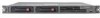
hp ProLiant DL320 generation 2 server high-density deployment technical white paper 24 6x FE 35 x FE 18 x FE 17 x FE 105 x Cat 5 Cables Routed Outside Server Cabinet Uplink to Network Backbone Switches on top of Rack 12x GbE 2x GbE 24 Port Switch (22 FE + 2 GbE) 1 2x GbE 24 Port Switch (22 FE + 2 GbE) 2 48 Port Switch (44 FE + 4 GbE) 1 8 x FE 35 x FE Servers in Rack 48 Port Switch (44 FE + 4 GbE) 2 4x GbE Server 01 Server 02 Server 03 Server 18 Server 19 NIC 1 (GbE) Server 35 NIC 2 (GbE) iLO (FE) Figure 5. Configuration B (Maximum Flexibility) Ethernet Cable Diagram
-
 1
1 -
2
-
3
-
4
-
5
-
6
-
7
-
8
-
9
-
10
-
11
-
12
-
13
-
14
-
15
-
16
-
17
-
18
-
 19
19 -
 20
20 -
 21
21 -
 22
22 -
 23
23 -
 24
24 -
 25
25 -
 26
26 -
 27
27 -
 28
28 -
 29
29 -
30
-
31
-
32
-
33
-
34
-
35
-
36
-
37
-
38
-
39
 |
 |

hp ProLiant DL320 generation 2 server high-density deployment technical white paper
24
48 Port Switch
(44 FE + 4 GbE)
1
24 Port Switch
(22 FE + 2 GbE)
2
48 Port Switch
(44 FE + 4 GbE)
2
Server
01
Server
02
Server
03
Server
35
12x GbE
18 x FE
4x GbE
2x GbE
NIC 1 (GbE)
NIC 2 (GbE)
iLO (FE)
35 x FE
35 x FE
8 x FE
24 Port Switch
(22 FE + 2 GbE)
1
Server
18
Server
19
17 x FE
6x FE
2x GbE
Uplink to Network
Backbone
105 x Cat 5 Cables Routed Outside Server Cabinet
Servers in Rack
Switches on top of Rack
Figure 5.
Configuration B (Maximum Flexibility) Ethernet Cable Diagram