HP Dc5750 Hardware Reference Guide - dc5750 MT - Page 19
Populating DIMM Sockets, labeled XMM1, XMM2
 |
UPC - 883585056446
View all HP Dc5750 manuals
Add to My Manuals
Save this manual to your list of manuals |
Page 19 highlights
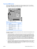
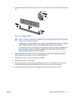
Populating DIMM Sockets There are four DIMM sockets on the system board, with two sockets per channel. The sockets are labeled XMM1, XMM2, XMM3, and XMM4. Sockets XMM1 and XMM3 operate in memory channel A. Sockets XMM2 and XMM4 operate in memory channel B. Figure 2-5 DIMM Socket Locations Item 1 2 3 4 Description DIMM socket XMM1, Channel A DIMM socket XMM2, Channel B DIMM socket XMM3, Channel A (populate first) DIMM socket XMM4, Channel B (populate second) Socket Color White White Black Black The system will automatically operate in single channel mode or dual channel mode, depending on how the DIMMs are installed. ● The system will operate in a higher-performing dual channel mode if like-sized DIMMs of equal capacity are populated in one or both pairs of sockets. For example, if the Channel A far socket and Channel B far socket (the two black sockets) both have 1024MB DIMMs installed, the system will operate in dual channel mode. If this system had two additional DIMMs added into the white sockets, they could be a pair of 256MB, 512MB, or 1024MB DIMMs and the system would still operate in dual channel mode. For purposes of "like sizes," a single-sided 512MB DIMM and a double-sided 512MB DIMM would not be the same size because they have different numbers of memory chips on them. ● The system will operate in single channel mode if the DIMMs are populated in any other supported configuration. Supported configurations consist of any combination of one, two, three, or four DIMMs as long as socket XMM3 is populated before socket XMM1 in Channel A, and socket XMM4 is populated before socket XMM2 in Channel B. ENWW Installing Additional Memory 13
-
 1
1 -
2
-
3
-
4
-
5
-
6
-
7
-
8
-
9
-
10
-
11
-
12
-
13
-
 14
14 -
 15
15 -
 16
16 -
 17
17 -
 18
18 -
 19
19 -
 20
20 -
 21
21 -
 22
22 -
 23
23 -
 24
24 -
25
-
26
-
27
-
28
-
29
-
30
-
31
-
32
-
33
-
34
-
35
-
36
-
37
-
38
-
39
-
40
-
41
-
42
-
43
-
44
-
45
-
46
-
47
-
48
-
49
-
50
-
51
-
52
 |
 |
