HP Designjet 3D HP Designjet 3D Printer Series Introductory Information - Page 3
Process, Printer Overview - removal system
 |
View all HP Designjet 3D manuals
Add to My Manuals
Save this manual to your list of manuals |
Page 3 highlights
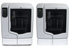
FDM® Process 1. From 3D CAD data, pre-processing software automatically slices, calculates support structures and creates tool paths that are optimized for the printer. 2. Parts are built layer by layer in an additive process. Dual extrusion heads precisely lay down thermoplastic model and support material to create each layer. 3. Temporary support structures are easily removed. Soluble support material automatically dissolves in a water-based solution. Printer Overview Front and left side views 1 6 2 5 3 4 1 Display panel 2 Material bay, support side 3 Optional material bay, support side 4 Optional material bay, model side 5 Material bay, model side 6 Power Switch 3
-
 1
1 -
 2
2 -
 3
3 -
 4
4 -
 5
5 -
 6
6 -
 7
7 -
 8
8 -
 9
9 -
10
-
11
-
12
-
13
-
14
-
15
-
16
-
17
-
18
-
19
-
20
-
21
-
22
-
23
-
24
-
25
-
26
-
27
-
28
-
29
-
30
-
31
-
32
-
33
-
34
-
35
-
36
-
37
-
38
-
39
-
40
-
41
-
42
-
43
-
44
-
45
-
46
-
47
-
48
-
49
-
50
-
51
-
52
-
53
-
54
-
55
 |
 |

3
FDM
®
Process
1.
From 3D CAD data, pre-processing software automatically slices, calculates support structures and
creates tool paths that are optimized for the printer.
2.
Parts are built layer by layer in an additive process. Dual extrusion heads precisely lay down thermo-
plastic model and support material to create each layer.
3.
Temporary support structures are easily removed. Soluble support material automatically dissolves in a
water-based solution.
Printer Overview
Front and left side views
1
Display panel
2
Material bay, support side
3
Optional material bay, support side
4
Optional material bay, model side
5
Material bay, model side
6
Power Switch
3
2
1
4
5
6