HP Dx7500 Hardware Reference Guide - dx7500 Microtower Model
HP Dx7500 - Compaq Business Desktop Manual
 |
UPC - 884420980605
View all HP Dx7500 manuals
Add to My Manuals
Save this manual to your list of manuals |
HP Dx7500 manual content summary:
- HP Dx7500 | Hardware Reference Guide - dx7500 Microtower Model - Page 1
Hardware Reference Guide - dx7500 Microtower Model HP Compaq Business PC - HP Dx7500 | Hardware Reference Guide - dx7500 Microtower Model - Page 2
Windows, and Windows Vista are either trademarks or registered trademarks of Microsoft Corporation in the United States and/or other countries. The only warranties for HP products and services Company. Hardware Reference Guide HP Compaq Business PC dx7500 Microtower Model First Edition (August 2008) - HP Dx7500 | Hardware Reference Guide - dx7500 Microtower Model - Page 3
About This Book This guide provides basic information for upgrading this computer model. WARNING! Text set off in this manner indicates that failure to follow directions could result in bodily harm or loss of life. CAUTION: Text - HP Dx7500 | Hardware Reference Guide - dx7500 Microtower Model - Page 4
iv About This Book ENWW - HP Dx7500 | Hardware Reference Guide - dx7500 Microtower Model - Page 5
the Windows Logo Key 5 Serial Number Location ...7 2 Hardware Upgrades Warnings and Cautions ...8 Removing the Computer Access Panel 9 Replacing the Computer Access Panel 10 Removing the Front Bezel ...11 Removing Bezel Blanks ...12 Replacing the Front Bezel ...13 Installing Additional Memory - HP Dx7500 | Hardware Reference Guide - dx7500 Microtower Model - Page 6
B Battery Replacement Appendix C External Security Devices Installing a Security Lock ...44 Cable Lock ...44 Padlock ...45 HP Business PC Security Lock 45 Appendix D Electrostatic Discharge Preventing Electrostatic Damage ...48 Grounding Methods ...48 Appendix E Computer Operating Guidelines - HP Dx7500 | Hardware Reference Guide - dx7500 Microtower Model - Page 7
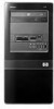
listing of the hardware and software installed in the computer, run the diagnostic utility (included on some computer models only). Instructions for using the utility are provided in the Troubleshooting Guide. Figure 1-1 HP Compaq dx7500 Microtower NOTE: The drive configuration shown above may be - HP Dx7500 | Hardware Reference Guide - dx7500 Microtower Model - Page 8
1 5.25-inch Optical Drives1 6 Hard Drive Activity Light 2 Optical Drive Activity Lights 7 Optical Drive Eject Buttons 3 3.5-inch Media Card Reader (optional)2 8 Headphone Connector 4 Microphone Connector 9 USB (Universal Serial Bus) 2.0 Ports 5 Dual-State Power Button 10 1394 Port - HP Dx7500 | Hardware Reference Guide - dx7500 Microtower Model - Page 9
7 MS PRO/MS PRO DUO ● Memory Stick (MS) ● Memory Stick Select ● Memory Stick PRO ● MagicGate Memory Stick (MG) ● Memory Stick Duo (MS Duo) Duo (MS PRO Duo) ● Memory Stick PRO- ● MagicGate Memory ● Memory Stick PRO HG Duo Duo (MS PRO) ● Memory Stick Micro (M2) (adapter required) ENWW - HP Dx7500 | Hardware Reference Guide - dx7500 Microtower Model - Page 10
Select Switch 9 Line-Out Connector for powered audio devices (green) 3 Line-In Audio Connector (blue) 10 Microphone Connector (pink) 4 RJ-45 Network Connector 11 Universal Serial Bus (USB) Ports 5 1394 Port 12 DVI Monitor Connector (white) 6 VGA Monitor Connector (blue) 13 Digital Line-In - HP Dx7500 | Hardware Reference Guide - dx7500 Microtower Model - Page 11
software you Windows XP and Microsoft Windows Vista. Windows Logo Key Displays or hides the Start menu Windows Logo Key + d Displays the Desktop Windows Logo Key + m Minimizes all open applications Shift + Windows Logo Key + m Undoes Minimize All Windows Logo Key + e Launches My Computer - HP Dx7500 | Hardware Reference Guide - dx7500 Microtower Model - Page 12
if you are not connected to a network domain Windows Logo Key + r Launches the Run dialog box Windows Logo Key + u Launches the Utility Manager Windows Logo Key + Pause/Break Launches the System Properties dialog box Windows Logo Key + Tab Windows XP - Cycles through the Taskbar buttons - HP Dx7500 | Hardware Reference Guide - dx7500 Microtower Model - Page 13
Serial Number Location Each computer has a unique serial number and product ID number that are located on the upper left side of the computer. Keep these numbers available for use when contacting customer service for assistance. Figure 1-6 Serial Number and Product ID Location ENWW Serial Number - HP Dx7500 | Hardware Reference Guide - dx7500 Microtower Model - Page 14
upgrades be sure to carefully read all of the applicable instructions, cautions, and warnings in this guide. WARNING! To reduce the risk of personal injury from electrical shock, hot surfaces, or fire: Disconnect the power network interface controller (NIC) receptacles. Do not disable the power cord - HP Dx7500 | Hardware Reference Guide - dx7500 Microtower Model - Page 15
the system is plugged into an active AC outlet. You must disconnect the power cord to avoid damage to the internal components of the computer. 5. Remove the screw (1) that secures the access panel to the computer chassis. 6. Slide the access panel back (2) about 1.3 cm (1/2 inch), then lift it off - HP Dx7500 | Hardware Reference Guide - dx7500 Microtower Model - Page 16
and slide it into place (1). Ensure that the hole for the screw is aligned with the hole in the chassis and tighten the screw (2). Figure 2-2 Replacing the Computer Access Panel 10 Chapter 2 Hardware Upgrades ENWW - HP Dx7500 | Hardware Reference Guide - dx7500 Microtower Model - Page 17
on the system board as long as the system is plugged into an active AC outlet. You must disconnect the power cord to avoid damage to the internal components of the computer. 5. Remove the computer access panel. 6. Press outward on the three latches on the right side of the bezel (1), then rotate the - HP Dx7500 | Hardware Reference Guide - dx7500 Microtower Model - Page 18
Bezel Blanks On some models, there are bezel blanks covering the 3.5-inch and 5.25-inch external drive bays that need to be removed before installing a drive. To remove a bezel blank: 1. Follow the instructions described in Removing the Front Bezel on page 11. 2. Press the two retaining tabs towards - HP Dx7500 | Hardware Reference Guide - dx7500 Microtower Model - Page 19
Replacing the Front Bezel Insert the three hooks on the left side of the bezel into the slots on the chassis (1) and rotate the bezel on from left to right (2) so that it snaps in place. Figure 2-5 Replacing the Front Bezel ENWW Replacing the Front Bezel 13 - HP Dx7500 | Hardware Reference Guide - dx7500 Microtower Model - Page 20
achieve the maximum memory support, you can populate the system board with up to 8-GB of memory configured in a highperforming dual channel mode. mandatory JEDEC SPD information In addition, the computer supports: ● 512Mbit, 1Gbit, and 2Gbit non-ECC memory technologies ● single-sided and double-sided - HP Dx7500 | Hardware Reference Guide - dx7500 Microtower Model - Page 21
the DIMM sockets are populated in one channel only. ● The system will operate in a higher-performing dual channel mode if the total memory capacity of the DIMMs in Channel A is equal to the total memory capacity of the DIMMs in Channel B. The technology and device width can vary between the channels - HP Dx7500 | Hardware Reference Guide - dx7500 Microtower Model - Page 22
With this configuration, 2GB will run as dual channel and 512MB will run as single power cord and wait approximately 30 seconds for the power to drain before adding or removing memory modules. Regardless of the power-on state, voltage is always supplied to the memory modules as long as the computer - HP Dx7500 | Hardware Reference Guide - dx7500 Microtower Model - Page 23
7 and 8 to install any additional modules. 10. Replace the computer access panel. 11. Reconnect the power cord and any external devices, then turn on the computer. The computer should automatically recognize the additional memory when you turn on the computer. 12. Lock any security devices that were - HP Dx7500 | Hardware Reference Guide - dx7500 Microtower Model - Page 24
of the power-on state, voltage is always present on the system board as long as the system is plugged into an active AC outlet. You must disconnect the power cord to avoid damage to the internal components of the computer. 5. Remove the computer access panel. 18 Chapter 2 Hardware Upgrades ENWW - HP Dx7500 | Hardware Reference Guide - dx7500 Microtower Model - Page 25
6. Locate the correct vacant expansion socket on the system board and the corresponding expansion slot on the back of the computer chassis. 7. On the rear of the computer, a slot cover lock secures the expansion card brackets in place. Remove the screw from the slot cover lock then slide the slot - HP Dx7500 | Hardware Reference Guide - dx7500 Microtower Model - Page 26
b. If you are removing a PCI Express x1 card, hold the card at each end and carefully rock it back and forth until the connectors pull free from the socket. Be sure not to scrape the card against the other components. Figure 2-11 Removing a PCI Express x1 Expansion Card 20 Chapter 2 Hardware - HP Dx7500 | Hardware Reference Guide - dx7500 Microtower Model - Page 27
the card and carefully rock the card back and forth until the connectors pull free from the socket. Be sure not to scrape the card against the other components the open slot. CAUTION: After removing an expansion card, you must replace it with a new card or expansion slot cover for proper cooling of - HP Dx7500 | Hardware Reference Guide - dx7500 Microtower Model - Page 28
rear of the chassis so that the bottom of the bracket on the card slides into the small slot on the chassis. Press the card straight down into the expansion socket on the system cables to the system board, if needed. 14. Replace the computer access panel. 22 Chapter 2 Hardware Upgrades ENWW - HP Dx7500 | Hardware Reference Guide - dx7500 Microtower Model - Page 29
Guide for instructions on using Computer Setup. Drive Positions Figure 2-15 Drive Positions 1 Two 5.25-inch external drive bays for optional drives (optical drives shown) 2 One 3.5-inch external drive bay for optional drive (media card reader shown) 3 Primary 3.5-inch internal hard drive bay - HP Dx7500 | Hardware Reference Guide - dx7500 Microtower Model - Page 30
the drives in the drive cage. Hard drives use 6-32 standard screws. All other drives use M3 metric screws. The HP-supplied M3 metric guide screws (1) are black. The HP-supplied 6-32 standard screws (2) are silver. Figure 2-16 Extra Drive Retainer Screws Location 24 Chapter 2 Hardware Upgrades ENWW - HP Dx7500 | Hardware Reference Guide - dx7500 Microtower Model - Page 31
not drop it. Do not use excessive force when inserting a drive. Avoid exposing a hard drive to liquids, temperature extremes, or products that have magnetic fields such as monitors or speakers. If a drive must be mailed, place the drive in a bubble-pack mailer or other protective packaging and label - HP Dx7500 | Hardware Reference Guide - dx7500 Microtower Model - Page 32
the power cord to avoid damage to the internal components of the computer. 5. Remove the access panel and front bezel. 6. Disconnect the power cable (1) and data cable (2) from the rear of the optical drive. Figure 2-18 Disconnecting the Power and Data Cables 26 Chapter 2 Hardware Upgrades ENWW - HP Dx7500 | Hardware Reference Guide - dx7500 Microtower Model - Page 33
as the system is plugged into an active AC outlet. You must disconnect the power cord to avoid damage to the internal components of the computer. 5. Remove the access panel and front bezel. 6. If you are installing a drive in a bay covered by a bezel blank, remove the front bezel then remove the - HP Dx7500 | Hardware Reference Guide - dx7500 Microtower Model - Page 34
cable (1) and data cable (2) to the rear of the optical drive. Figure 2-21 Connecting the Power and Data Cables 12. Replace the front bezel and access panel. 13. Reconnect the power cord and turn on the computer. 14. Lock any security devices that were disengaged when the access panel was removed - HP Dx7500 | Hardware Reference Guide - dx7500 Microtower Model - Page 35
as the system is plugged into an active AC outlet. You must disconnect the power cord to avoid damage to the internal components of the computer. 5. Remove the access panel and front bezel. 6. Disconnect the drive cables, as indicated in the following illustrations: a. If you are removing a diskette - HP Dx7500 | Hardware Reference Guide - dx7500 Microtower Model - Page 36
from the system board. Figure 2-23 Disconnecting the Media Card Reader Cable 7. Remove the two retainer screws that secure the drive to the bay (1) then slide the drive forward and out of the bay (2). Figure 2-24 Removing a 3.5-inch Device (Media Card Reader Shown) NOTE: To install an external - HP Dx7500 | Hardware Reference Guide - dx7500 Microtower Model - Page 37
as the system is plugged into an active AC outlet. You must disconnect the power cord to avoid damage to the internal components of the computer. 5. Remove the access panel and front bezel. 6. If you are installing a diskette drive or media card reader in a bay covered by a bezel blank, remove the - HP Dx7500 | Hardware Reference Guide - dx7500 Microtower Model - Page 38
the new hard drive. Also, if you are replacing the primary hard drive, make sure you have created a Recovery Disc Set to restore the operating system, software drivers, and any software applications that were preinstalled on the computer. If you do not have this CD set, select Start > HP Backup and - HP Dx7500 | Hardware Reference Guide - dx7500 Microtower Model - Page 39
screws that secure the hard drive cage to the chassis. Figure 2-26 Removing the Hard Drive Cage Screws 7. Push down the latch on the side of the hard drive cage (1), then slide the hard drive cage away from the bottom of the chassis (2) as shown below. Figure 2-27 Releasing the Hard Drive Cage ENWW - HP Dx7500 | Hardware Reference Guide - dx7500 Microtower Model - Page 40
8. Lift the hard drive cage out of the chassis. Figure 2-28 Removing the Hard Drive Cage 9. Disconnect the power cable (1) and data cable (2) from the back of the hard drive. Figure 2-29 Disconnecting the Hard Drive Cables 34 Chapter 2 Hardware Upgrades ENWW - HP Dx7500 | Hardware Reference Guide - dx7500 Microtower Model - Page 41
four screws that secure the hard disk drive to the hard drive cage (1), then slide the hard disk drive out of the hard drive cage (2). Figure 2-30 Removing the Hard Drive NOTE: To install an internal 3.5-inch hard drive, refer to Installing an Internal 3.5-inch Hard Drive on page 35. Installing an - HP Dx7500 | Hardware Reference Guide - dx7500 Microtower Model - Page 42
standard screws that secure the hard disk drive to the hard drive cage (2). Make sure the hard disk drive cables are facing the top of the drive cage. NOTE: If you are replacing an old drive with a new drive, use the four retainer screws from the old drive to install the new drive. NOTE: If you are - HP Dx7500 | Hardware Reference Guide - dx7500 Microtower Model - Page 43
3. Connect the power cable (1) and data cable (2) to the back of the hard drive. Figure 2-32 Connecting the Hard Drive Cables CAUTION: Never crease or bend a SATA data cable tighter than a 30 mm (1.18 in) radius. A sharp bend can break the internal wires. 4. Place the hard drive cage into the - HP Dx7500 | Hardware Reference Guide - dx7500 Microtower Model - Page 44
devices that were disengaged when the access panel was removed. NOTE: If you are replacing the primary hard drive, use the Recovery Disc Set to restore the operating system, software drivers, and any software applications that were preinstalled on the computer. 38 Chapter 2 Hardware Upgrades ENWW - HP Dx7500 | Hardware Reference Guide - dx7500 Microtower Model - Page 45
Specifications Table A-1 Specifications Desktop (noncondensing) Operating 10-90% 10-90% Nonoperating (38.7°C max wet bulb) 5-95% 5-95% Maximum Altitude (unpressurized) Operating Typical (idle) 307 BTU/hr 77 kg-cal/hr Power Supply 115V 230V Operating Voltage Range1 90-132 VAC 180-264 - HP Dx7500 | Hardware Reference Guide - dx7500 Microtower Model - Page 46
Table A-1 Specifications (continued) Rated Input Current (maximum)1 8A @ 100 VAC 4A @ 200 VAC 1 This system utilizes a passive power factor corrected power supply. The power factor correction is present in the 230V operating mode only. This allows the system to pass the CE mark requirements for - HP Dx7500 | Hardware Reference Guide - dx7500 Microtower Model - Page 47
water. Replace the battery only with the HP spare designated for this product. CAUTION: Before replacing the battery, it is important to back up the computer CMOS settings. When the battery is removed or replaced, the CMOS settings will be cleared. Refer to the Computer Setup (F10) Utility Guide for - HP Dx7500 | Hardware Reference Guide - dx7500 Microtower Model - Page 48
NOTE: On some computer models, it may be necessary to remove an internal component to gain access to the battery. 7. Depending on the type of battery holder on the system board, complete the following instructions to replace the battery. Type 1 a. Lift the battery out of its holder. Figure B-1 - HP Dx7500 | Hardware Reference Guide - dx7500 Microtower Model - Page 49
to complete this procedure. 8. Replace the computer access panel. 9. Plug in the computer and turn on power to the computer. 10. Reset the date and time, your passwords, and any special system setups using Computer Setup. Refer to the Computer Setup (F10) Utility Guide. 11. Lock any security devices - HP Dx7500 | Hardware Reference Guide - dx7500 Microtower Model - Page 50
For information on data security features, refer to the Computer Setup (F10) Utility Guide and the Desktop Management Guide. Installing a Security Lock The security locks displayed below and on the following pages can be used to secure the computer. Cable Lock Figure C-1 Installing a Cable Lock 44 - HP Dx7500 | Hardware Reference Guide - dx7500 Microtower Model - Page 51
Padlock Figure C-2 Installing a Padlock HP Business PC Security Lock 1. Fasten the security cable by looping it around a stationary object. Figure C-3 Securing the Cable to a Fixed Object ENWW Installing a Security Lock 45 - HP Dx7500 | Hardware Reference Guide - dx7500 Microtower Model - Page 52
2. Thread the keyboard and mouse cables through the lock. Figure C-4 Threading the Keyboard and Mouse Cables 3. Screw the lock to the chassis using the screw provided. Figure C-5 Attaching the Lock to the Chassis 46 Appendix C External Security Devices ENWW - HP Dx7500 | Hardware Reference Guide - dx7500 Microtower Model - Page 53
4. Insert the plug end of the security cable into the lock (1) and push the button in (2) to engage the lock. Use the key provided to disengage the lock. Figure C-6 Engaging the Lock ENWW Installing a Security Lock 47 - HP Dx7500 | Hardware Reference Guide - dx7500 Microtower Model - Page 54
until they arrive at static-free workstations. ● Place parts cord to a grounded workstation or computer chassis. Wrist straps are flexible HP authorized dealer, reseller, or service provider. NOTE: For more information on static electricity, contact an HP authorized dealer, reseller, or service - HP Dx7500 | Hardware Reference Guide - dx7500 Microtower Model - Page 55
and keyboard. ● Never cover the ventilation slots on the monitor with any type of material. ● Install or enable power management functions of the operating system or other software, including sleep states. ● Turn off the computer before you do either of the following: ◦ Wipe the exterior of the - HP Dx7500 | Hardware Reference Guide - dx7500 Microtower Model - Page 56
or liquid falls into the drive, immediately unplug the computer and have it checked by an authorized HP service provider. Shipping Preparation Follow these suggestions when preparing to ship the computer: 1. Back up the hard drive files on PD discs, tape cartridges, CDs, or diskettes. Be sure that - HP Dx7500 | Hardware Reference Guide - dx7500 Microtower Model - Page 57
31 removing 29 memory installing 14 populating sockets 15 specifications 14 microphone connector 2, 4 monitor connector DVI 4 VGA 4 mouse connector 4 N network connector 4 O optical drive cleaning 50 installing 27 precautions 50 removing 26 P PCI Express card 18, 21 power supply 39 product ID - HP Dx7500 | Hardware Reference Guide - dx7500 Microtower Model - Page 58
front bezel 11 hard drive 32 media card reader 29 optical drive 26 PCI Express x1 card 20 PCI Express x16 card 21 S security cable lock 44 HP Business PC Security Lock 45 padlock 45 serial number location 7 serviceability features 1 shipping preparation 50 specifications computer 39 memory 14 system
-
 1
1 -
 2
2 -
 3
3 -
 4
4 -
 5
5 -
 6
6 -
 7
7 -
8
-
9
-
10
-
11
-
12
-
13
-
14
-
15
-
16
-
17
-
18
-
19
-
20
-
21
-
22
-
23
-
24
-
25
-
26
-
27
-
28
-
29
-
30
-
31
-
32
-
33
-
34
-
35
-
36
-
37
-
38
-
39
-
40
-
41
-
42
-
43
-
44
-
45
-
46
-
47
-
48
-
49
-
50
-
51
-
52
-
53
-
54
-
55
-
56
-
57
-
58
 |
 |

Hardware Reference Guide - dx7500
Microtower Model
HP Compaq Business PC