HP ENVY 15-3217nr HP ENVY 15 - Maintenance and Service Guide - Page 51
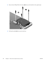
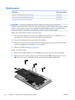
Remove the two Phillips PM2.0×2.8 screws that secure the WLAN module to the system board.
 |
View all HP ENVY 15-3217nr manuals
Add to My Manuals
Save this manual to your list of manuals |
Page 51 highlights
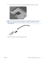
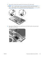
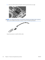
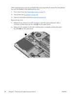
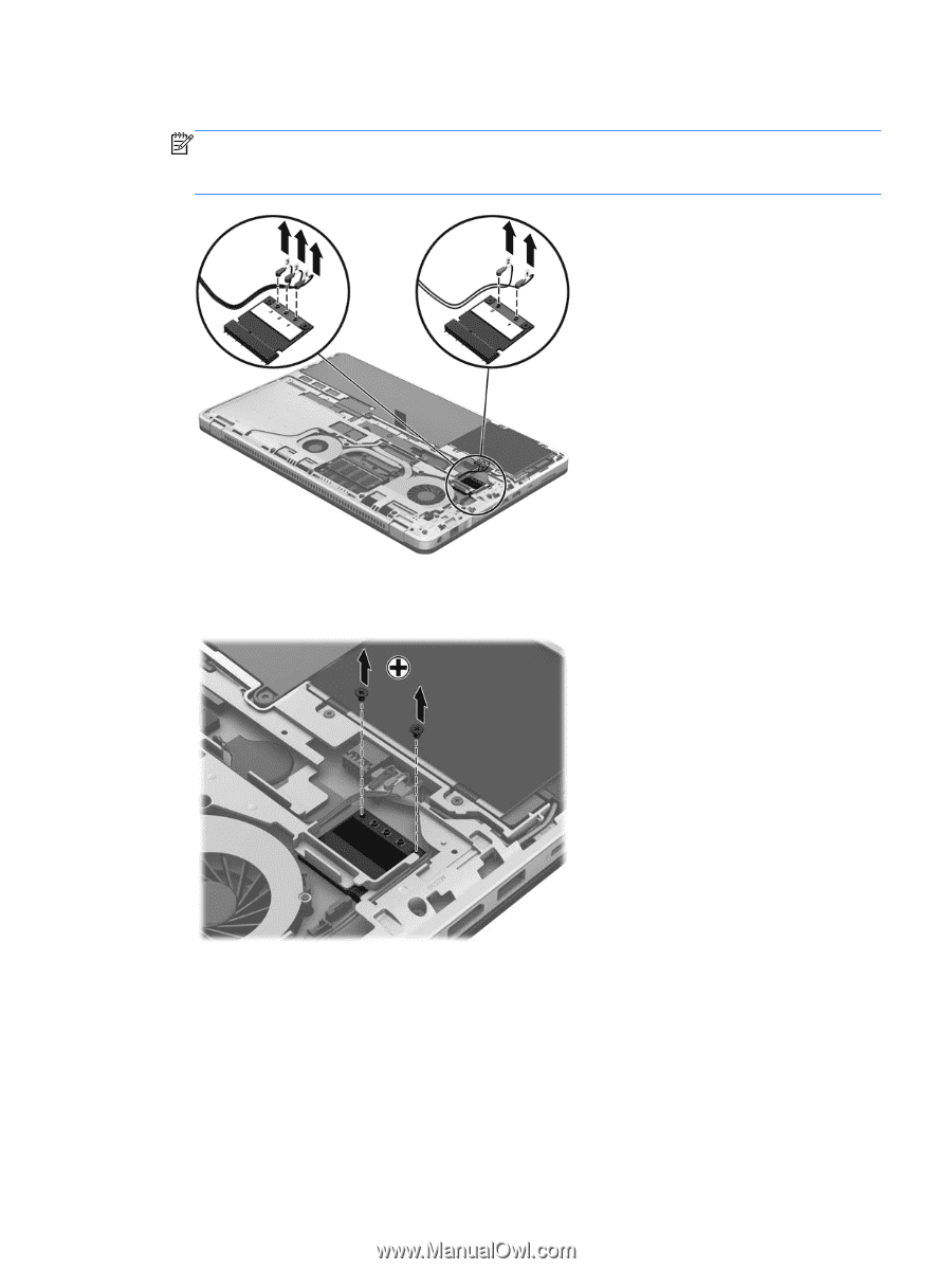
3. Disconnect the wireless antenna cables from the terminals on the WLAN module. NOTE: The "1" wireless antenna cable is connected to the WLAN module Main terminal. The "2" wireless antenna cable is connected to the WLAN module Aux terminal. If a third wireless antenna cable is present, it is connected to the WLAN module middle terminal. 4. Remove the two Phillips PM2.0×2.8 screws that secure the WLAN module to the system board. (The WLAN module tilts up.) ENWW Component replacement procedures 43
-
 1
1 -
2
-
3
-
4
-
5
-
6
-
7
-
8
-
9
-
10
-
11
-
12
-
13
-
14
-
15
-
16
-
17
-
18
-
19
-
20
-
21
-
22
-
23
-
24
-
25
-
26
-
27
-
28
-
29
-
30
-
31
-
32
-
33
-
34
-
35
-
36
-
37
-
38
-
39
-
40
-
41
-
42
-
43
-
44
-
45
-
 46
46 -
 47
47 -
 48
48 -
 49
49 -
 50
50 -
 51
51 -
 52
52 -
 53
53 -
 54
54 -
 55
55 -
 56
56 -
57
-
58
-
59
-
60
-
61
-
62
-
63
-
64
-
65
-
66
-
67
-
68
-
69
-
70
-
71
-
72
-
73
-
74
-
75
-
76
-
77
-
78
-
79
-
80
-
81
-
82
-
83
-
84
-
85
-
86
-
87
-
88
-
89
-
90
-
91
-
92
-
93
-
94
-
95
-
96
-
97
-
98
-
99
-
100
-
101
-
102
-
103
-
104
-
105
-
106
-
107
-
108
-
109
-
110
-
111
-
112
-
113
-
114
-
115
-
116
-
117
-
118
-
119
-
120
-
121
-
122
-
123
-
124
 |
 |
3.
Disconnect the wireless antenna cables from the terminals on the WLAN module.
NOTE:
The “1” wireless antenna cable is connected to the WLAN module Main terminal.
The “2” wireless antenna cable is connected to the WLAN module Aux terminal. If a third wireless
antenna cable is present, it is connected to the WLAN module middle terminal.
4.
Remove the two Phillips PM2.0×2.8 screws that secure the WLAN module to the system board.
(The WLAN module tilts up.)
ENWW
Component replacement procedures
43