HP ENVY 17-k011nr HP ENVY 17 Notebook PC HP ENVY 15 Notebook PC - Maintenance - Page 86
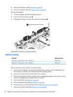
Power connector cable, Release the metal clip to disconnect the power connector cable
 |
View all HP ENVY 17-k011nr manuals
Add to My Manuals
Save this manual to your list of manuals |
Page 86 highlights
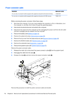
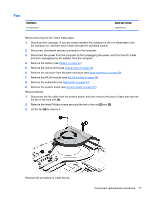
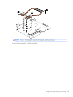
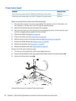
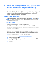
Power connector cable Description For use only on computer models equipped with a graphics subsystem with discrete memory For use only on computer models equipped with a graphics subsystem with UMA memory Spare part number 720240-001 720241-001 Before removing the power connector, follow these steps: 1. Shut down the computer. If you are unsure whether the computer is off or in Hibernation, turn the computer on, and then shut it down through the operating system. 2. Disconnect all external devices connected to the computer. 3. Disconnect the power from the computer by first unplugging the power cord from the AC outlet and then unplugging the AC adapter from the computer. 4. Remove the battery (see Battery on page 42), 5. Remove the optical drive (see Optical drive on page 43). 6. Remove the top cover from the base enclosure (see Base enclosure on page 46). 7. Remove the WLAN module (see WLAN module on page 59). 8. Remove the subwoofer (see Subwoofer on page 63). 9. Remove the system board (see System board on page 67). Remove the power connector cable: 1. Release the metal clip to disconnect the power connector cable (1) from the system board. 2. Disengage the cable from the clips (2). 3. Release the clips (3), and then remove the power connector cable (4). Reverse this procedure to install the power connector cable and bracket. 76 Chapter 6 Removal and replacement procedures for Authorized Service Provider parts
-
 1
1 -
2
-
3
-
4
-
5
-
6
-
7
-
8
-
9
-
10
-
11
-
12
-
13
-
14
-
15
-
16
-
17
-
18
-
19
-
20
-
21
-
22
-
23
-
24
-
25
-
26
-
27
-
28
-
29
-
30
-
31
-
32
-
33
-
34
-
35
-
36
-
37
-
38
-
39
-
40
-
41
-
42
-
43
-
44
-
45
-
46
-
47
-
48
-
49
-
50
-
51
-
52
-
53
-
54
-
55
-
56
-
57
-
58
-
59
-
60
-
61
-
62
-
63
-
64
-
65
-
66
-
67
-
68
-
69
-
70
-
71
-
72
-
73
-
74
-
75
-
76
-
77
-
78
-
79
-
80
-
 81
81 -
 82
82 -
 83
83 -
 84
84 -
 85
85 -
 86
86 -
 87
87 -
 88
88 -
 89
89 -
 90
90 -
 91
91 -
92
-
93
-
94
-
95
-
96
-
97
-
98
-
99
-
100
-
101
-
102
-
103
-
104
-
105
-
106
-
107
-
108
-
109
-
110
-
111
-
112
-
113
-
114
-
115
-
116
-
117
-
118
 |
 |