HP ENVY 17-n000 Maintenance and Service Guide 1 - Page 45
Remove the Phillips M2.0 × 2.5 screw, Remove the WLAN module shield
 |
View all HP ENVY 17-n000 manuals
Add to My Manuals
Save this manual to your list of manuals |
Page 45 highlights
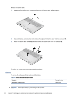
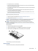
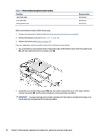
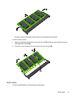
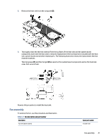
Table 5-4 WLAN module descriptions and part numbers Description Intel Wireless Wi-Fi6e AX 211 Wi-Fi + Bluetooth® 5, M.2 2230 (non-vPro) Mediatek Tequila MT7921 Wi-Fi 6 + Bluetooth 5.2 M.2 2230 PCI-e + USB with WLAN Transparent WLAN shield Spare part number M53366-005 M53366-005 N10779-001 IMPORTANT: To prevent an unresponsive system, replace the wireless module only with a wireless module authorized for use in the computer by the governmental agency that regulates wireless devices in your country or region. If you replace the module and then receive a warning message, remove the module to restore device functionality, and then contact technical support. Before removing the WLAN module, follow these steps: 1. Prepare the computer for disassembly (see Preparation for disassembly on page 33). 2. Remove the bottom cover (see Bottom cover on page 33). 3. Remove the battery (see Battery on page 34). Remove the WLAN module: 1. Remove the WLAN module shield (1). The WLAN module shield is available using spare part number N10779-001. 2. Carefully disconnect the two antenna cables from the module (2). 3. Remove the Phillips M2.0 × 2.5 screw (3) that secures the WLAN module to the system board. 4. Remove the WLAN module (4). NOTE: Models have either one or two WLAN antennas. On models with two antennas, the #1 white WLAN antenna cable connects to the WLAN module #1 Main terminal. The #2 black WLAN antenna cable connects to the WLAN module #1 Aux terminal. 38 Chapter 5 Removal and replacement procedures for authorized service provider parts
-
 1
1 -
2
-
3
-
4
-
5
-
6
-
7
-
8
-
9
-
10
-
11
-
12
-
13
-
14
-
15
-
16
-
17
-
18
-
19
-
20
-
21
-
22
-
23
-
24
-
25
-
26
-
27
-
28
-
29
-
30
-
31
-
32
-
33
-
34
-
35
-
36
-
37
-
38
-
39
-
 40
40 -
 41
41 -
 42
42 -
 43
43 -
 44
44 -
 45
45 -
 46
46 -
 47
47 -
 48
48 -
 49
49 -
 50
50 -
51
-
52
-
53
-
54
-
55
-
56
-
57
-
58
-
59
-
60
-
61
-
62
-
63
-
64
-
65
-
66
-
67
-
68
-
69
-
70
-
71
-
72
-
73
-
74
-
75
-
76
-
77
-
78
-
79
-
80
-
81
-
82
-
83
-
84
-
85
-
86
-
87
-
88
-
89
-
90
 |
 |