HP ENVY TouchSmart Sleekbook 4-1115dx HP ENVY 4 Sleekbook HP ENVY 4 Ultrabook - Page 47
Component replacement procedures, Display panel
 |
View all HP ENVY TouchSmart Sleekbook 4-1115dx manuals
Add to My Manuals
Save this manual to your list of manuals |
Page 47 highlights
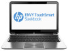
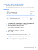
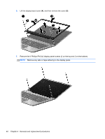
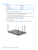
Component replacement procedures This chapter provides removal and replacement procedures. There are as many as 77 screws that must be removed, replaced, or loosened when servicing the computer. Make special note of each screw size and location during removal and replacement. Display panel Description 14.0 in, WLED, BrightView SVA display panel In black finish for use with touch models only In black finish for use with non-touch models only In black and silver finish for use with non-touch models only Spare part number 699378-001 716398-001 702683-001 716399-001 702684-001 716400-001 Before removing the display panel, follow these steps: 1. Shut down the computer. If you are unsure whether the computer is off or in Hibernation, turn the computer on, and then shut it down through the operating system. 2. Disconnect all external devices connected to the computer. 3. Disconnect the power from the computer by first unplugging the power cord from the AC outlet and then unplugging the AC adapter from the computer. Remove the display panel: 1. Turn the computer right-side up, with the rear toward you. 2. Open the computer. 3. Remove the 2 screw covers (1) on the left and right side base of the display panel. NOTE: Use a sharp probe to pop the covers out to avoid scratching the bezel 4. Remove the 2 Phillips PM 2.5x3 screws (2) on the left and right hinges that secure the display panel to the computer. NOTE: Support the display panel as you are removing the screws. 5. Loosen the edges of the plastic bezel cover (3) from all four sides of the display panel. Component replacement procedures 39
-
 1
1 -
2
-
3
-
4
-
5
-
6
-
7
-
8
-
9
-
10
-
11
-
12
-
13
-
14
-
15
-
16
-
17
-
18
-
19
-
20
-
21
-
22
-
23
-
24
-
25
-
26
-
27
-
28
-
29
-
30
-
31
-
32
-
33
-
34
-
35
-
36
-
37
-
38
-
39
-
40
-
41
-
 42
42 -
 43
43 -
 44
44 -
 45
45 -
 46
46 -
 47
47 -
 48
48 -
 49
49 -
 50
50 -
 51
51 -
 52
52 -
53
-
54
-
55
-
56
-
57
-
58
-
59
-
60
-
61
-
62
-
63
-
64
-
65
-
66
-
67
-
68
-
69
-
70
-
71
-
72
-
73
-
74
-
75
-
76
-
77
-
78
-
79
-
80
-
81
-
82
-
83
-
84
-
85
-
86
-
87
-
88
-
89
-
90
-
91
-
92
-
93
-
94
-
95
-
96
-
97
-
98
-
99
-
100
-
101
-
102
-
103
-
104
-
105
-
106
-
107
-
108
-
109
-
110
-
111
-
112
-
113
-
114
-
115
-
116
 |
 |